
Separating anti-drop moving contact for molded case circuit breaker

A technology of molded case circuit breaker and moving contact piece, which is applied in the directions of circuit breaker contacts and circuit breaker parts, etc., can solve the problems of limited breaking current, difficulty in preventing contacts from falling, and limited improvement space.

Pending Publication Date: 2019-09-06
DELIXI ELECTRIC
View PDF0 Cites 1 Cited by
  • Summary
  • Abstract
  • Description
  • Claims
  • Application Information

AI Technical Summary

Problems solved by technology

After the contacts are repelled, due to the increasing distance between the dynamic and static contacts and the limited breaking current, the repulsion between the contacts will gradually decrease, and the reaction force spring of the contacts will increase appropriately, so that The repulsion force will be smaller than the spring reaction force. If the speed of the action mechanism is not fast enough at this time and the action is not in place, the moving contact piece will rotate in the direction of closing the static contact, that is, the phenomenon of contact falling occurs, causing the contact to open. The distance is reduced, causing the arc to reignite, causing the contact to be burned or even welded
[0003] In order to avoid the falling of the moving contact piece after being repelled, the following measures can generally be taken: use welding-resistant contact material, but the contact material has two sides. In the current situation, the welding-resistant function is realized, but the contact resistance It will inevitably increase, resulting in problems with temperature rise; reduce the response time of the operating mechanism and speed up the action, but there is limited room for improvement in the existing linkage mechanism; control the contact pressure, but the contact pressure decreases, repelling the meeting It becomes easy, and temperature rise is also prone to problems. If the pressure of the contacts increases, it will become difficult to repel, and it is still difficult to prevent the contacts from falling

Method used


Image

  • Separating anti-drop moving contact for molded case circuit breaker
  • Separating anti-drop moving contact for molded case circuit breaker
  • Separating anti-drop moving contact for molded case circuit breaker

Examples


Embodiment Construction

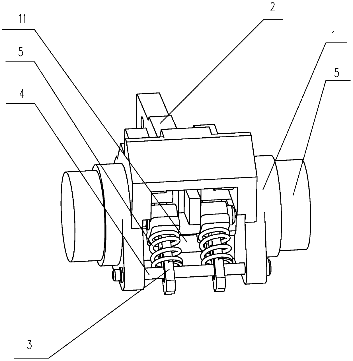
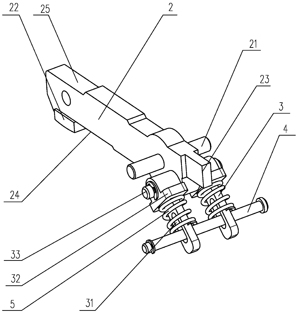
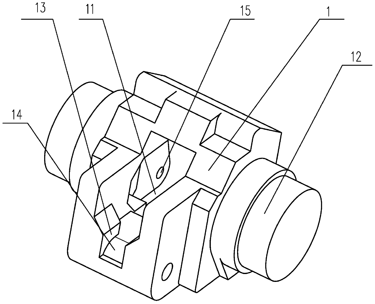
[0035] by Figure 1 to Figure 3 It can be seen that a breaking and anti-drop moving contact piece for a molded case circuit breaker is disclosed, which includes a connecting seat 1, two sides of the connecting seat 1 are formed with hinged protrusions 12 for articulation, and the upper edge of the connecting seat 1 An installation through groove 11 is formed in the front and rear direction, and a movable contact rod 2 is arranged in the installation through groove 11, and the movable contact rod 2 is hingedly arranged in the installation through groove 11 through a swing shaft 21. Both sides of the installation through groove 11 A swing groove is formed on the wall, the swing shaft 21 is inserted into the swing groove to form a movable contact rod 2 that swings in the installation through groove 11, and the front end of the movable contact rod 2 extends outside the installation through groove 11 and is arranged There is a moving contact piece 22, the rear end of the moving conta...


PUM


Abstract

The invention discloses a separating anti-drop moving contact for a molded case circuit breaker. The separating anti-drop moving contact comprises a connecting base. A mounting through groove is formed on the connecting base. A moving contact rod is arranged in the mounting through groove. The moving contact rod is hinged in the mounting through groove. The front end of the moving contact rod extends out of the mounting through groove and is provided with a moving contact. A slide rod is hinged on the rear end of the moving contact rod. The slide rod is hinged with the moving contact rod through a connecting pin. A travel groove is formed on the slide rod. A push rod is arranged on the travel groove in a penetrating way. The push rod is rotatably arranged in an accommodating cavity. An abutting spring sleeves on the slide rod. The abutting spring abuts between the push rod and the moving contact rod. The inclined angle between the connecting line of the connecting hole and the rotatingport and the horizontal plane is greater than the inclined angle between the connecting line of the swing groove and the connecting hole and the horizontal plane. The structure is simple, the movingcontact can be separated by repulsion under the short-circuit current and the situation that the moving contact falls back because of reduction of the electric repulsion due to increasing separating distance along with driving of the mechanism does not occur.

Description

Technical field [0001] The invention relates to the technical field of molded case circuit breaker parts, in particular to a movable contact piece with anti-drop function after breaking and repelling. Background technique [0002] As the breaking requirements of molded case circuit breakers increase, current limiting capabilities are required. Since the movement of the movable contact piece of the ordinary plastic case circuit breaker is determined by the action of the operating mechanism, then under the action of the short-circuit current, a strong electric repulsion force is generated between the moving and static contacts. The moving contact piece repels before the operating mechanism, and then the operating mechanism Move again, and drive the moving contact piece to continue moving away from the static contact. After the contacts are repelled, because the distance between the moving and static contacts is increasing, and the breaking current is limited, the repulsive force b...

Claims


Application Information

Patent Timeline
IPC IPC(8): H01H73/04
CPCH01H73/04
Inventor 袁亦峰
Owner DELIXI ELECTRIC
Learn More