Differential locking mechanism

A differential lock and differential gear technology, applied in the field of differential locking mechanism, can solve the problems of high technical and material requirements, complex locking process, slow response speed, etc., and achieve low technical and material requirements, simple structure, Responsive effect

Inactive Publication Date: 2019-09-06
郭放
View PDF10 Cites 2 Cited by
  • Summary
  • Abstract
  • Description
  • Claims
  • Application Information

AI Technical Summary

Problems solved by technology

[0002] At present, some of the existing differential locking mechanisms have complex structures, some require high technology and materials, are not easy to manufacture and are expensive, some have complicated locking processes, require parking or low speed to lock, and some have slow response speeds. Some structures have low strength and are not durable

Method used


Image

  • Differential locking mechanism
  • Differential locking mechanism

Examples


Embodiment 1

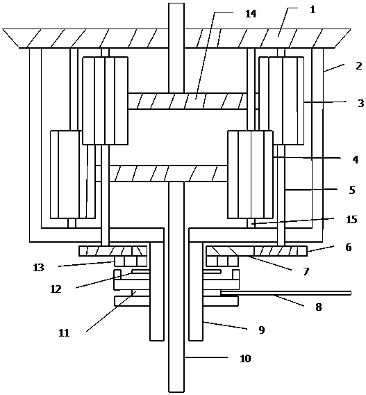
[0009] Now refer to the attached figure 1 , combined with embodiments described as follows: a differential locking mechanism, including a differential and a locking mechanism. Described differential includes driven gear 1, differential case 2, axle shaft 10, axle gear 14, planetary gear A3, planetary gear B4, planetary gear shaft 5, planetary gear shaft 15; Described differential One end of the case 2 is fixedly provided with a driven gear 1, and the two ends of the differential case 2 are respectively provided with half shafts 10 for rotation, and one end of the two half shafts 10 facing the inside of the differential case 2 is respectively fixedly provided with a half shaft Gear 14, the planetary gear A3 and the planetary gear B4 are arranged rotationally symmetrically around the side gear 14, and the planetary gear B4 is rotatably connected to the differential case 2 through the planetary gear shaft 15, and the planetary gear shaft 15 and the half shaft The shafts 10 are p...

Embodiment 2

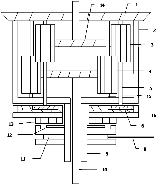
[0014] Now refer to the attached figure 2 , combined with embodiments described as follows: a differential locking mechanism, including a differential and a locking mechanism. Described differential includes driven gear 1, differential case 2, axle shaft 10, axle gear 14, planetary gear A3, planetary gear B4, planetary gear shaft 5, planetary gear shaft 15; Described differential One end of the case 2 is fixedly provided with a driven gear 1, and the two ends of the differential case 2 are respectively provided with half shafts 10 for rotation, and one end of the two half shafts 10 facing the inside of the differential case 2 is respectively fixedly provided with a half shaft Gear 14, the planetary gear A3 and the planetary gear B4 are arranged rotationally symmetrically around the side gear 14, and the planetary gear B4 is rotatably connected to the differential case 2 through the planetary gear shaft 15, and the planetary gear shaft 15 and the half shaft The shafts 10 are ...


PUM


Abstract

The invention discloses a differential locking mechanism. The differential locking mechanism comprises a differential and a locking structure. A gear C is fixedly arranged at the end, positioned outside a differential shell, of a planet gear shaft; a sleeve is fixedly arranged at one end of the differential shell; a gear D is arranged on the side, near the differential shell, of the sleeve in a sleeving manner; the gear D is rotationally connected with the sleeve; one end of the gear D is fixedly connected with a gear E; the gear E is rotationally connected with the sleeve; a longitudinal tooth groove is formed in the end, far from the differential shell, of the sleeve; a tooth sleeve is arranged on the tooth groove in a sleeving manner, is engaged with the tooth groove, and can move in the longitudinal direction of the tooth groove; teeth are arranged at one end of the tooth sleeve, and can be engaged with the gear E; an annular groove is arranged outside the tooth sleeve; and a poking fork is movably connected into the groove.

Description

technical field [0001] The invention relates to the field of auto parts, in particular to a differential locking mechanism. Background technique [0002] At present, some of the existing differential locking mechanisms have complex structures, some require high technology and materials, are not easy to manufacture and are expensive, some have complicated locking processes, require parking or low speed to lock, and some have slow response speeds. Some structures have low strength and are not durable. Contents of the invention [0003] The purpose of the present invention is to overcome the shortcomings of the prior art and provide a differential locking mechanism with a relatively simple structure and durability. It has low requirements on technology and materials, and is easy to manufacture and assemble. The locking operation is simple and responsive, and it can be locked without stopping or reducing the speed of the vehicle. It can be started manually, and can also b...

Claims


Application Information

Patent Timeline
Patent Type & Authority Applications(China)
IPC IPC(8): F16H48/24F16H48/10
CPCF16H48/24F16H48/10F16H2048/106F16H48/11
Inventor 郭放
Owner 郭放
Why Eureka
Try Eureka