A kind of drainage method based on siphon roof drainage structure

A roof drainage structure, siphon type technology, applied in the direction of roof drainage, roof, roof covering, etc., can solve the problems of difficult drainage of accumulated water, roof cracks, poor rainwater suction function, etc., to improve the service life and structural strength , Reduce the occurrence of roof cracks and improve the efficiency of roof drainage

Active Publication Date: 2020-09-11
SCEGC NO 5 CONSTRUCTION ENGINEERING GROUP COMPANYLTD
View PDF5 Cites 0 Cited by
  • Summary
  • Abstract
  • Description
  • Claims
  • Application Information

AI Technical Summary

Problems solved by technology

Although the efficiency of the siphon drainage system is much higher than that of the gravity drainage system, there are still some shortcomings in the siphon drainage system: first, the rainwater still carries a small part of the air into the rainwater bucket, first of all, the drainage efficiency is reduced , and when the air reaches the negative pressure area in the system, the pressure in the negative pressure area will increase, resulting in a poor suction function for rainwater in the negative pressure area, which will affect the drainage efficiency of the entire system; the second is the gap between the roof insulation layer and the waterproof layer The stagnant water is not easy to discharge, and it is easy to cause roof cracks; in addition, because the downpipe is directly buried in the roof, it is inconvenient to clean and replace it

Method used


Image

  • A kind of drainage method based on siphon roof drainage structure
  • A kind of drainage method based on siphon roof drainage structure
  • A kind of drainage method based on siphon roof drainage structure

Examples


Embodiment Construction

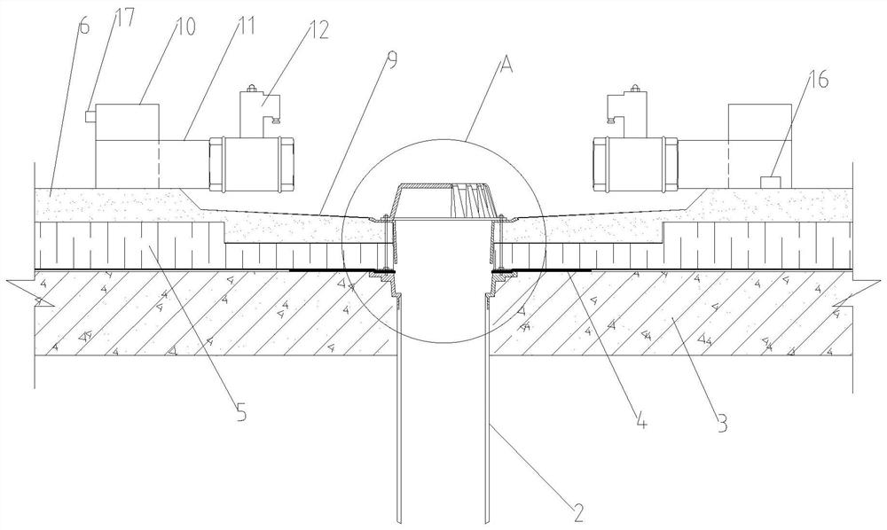
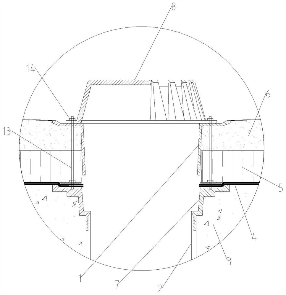
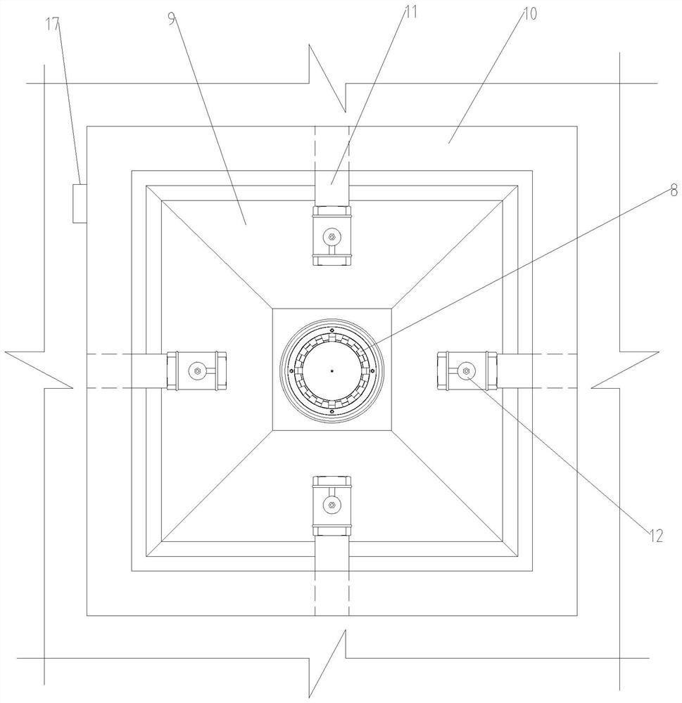
[0054] A drainage method based on a siphonic roof drainage structure, such as figure 1 with figure 2 As shown, the siphon type roof drainage structure includes a downspout 1 and a downpipe 2 installed in the roof, and the roof includes a concrete structure layer 3, a waterproof layer 4, an insulation layer 5 and a concrete surface layer 6 from bottom to top. The concrete surface layer 6 is provided with a sump 9 for the installation of the sink 1, the top of the sump 9 is provided with an annular anti-sill 10, and the annular anti-sill 10 is provided with a plurality of guide pipes 11, so One end of the guide tube 11 is flush with the outer wall of the annular anti-sill 10, the other end of the guide tube 11 extends into the interior of the annular anti-sill 10, and the upper end of the guide tube 11 extends into the interior of the annular anti-sill 10 A solenoid valve 12 is arranged on the section of the trough, and the falling water bucket 1 includes a frustum-shaped cyli...


PUM


Abstract

The invention discloses a drainage method based on a siphonic roofing drainage structure. The siphonic roofing drainage structure comprises gutter spout funnels and downspouts. The drainage method comprises the steps that first, the siphonic roofing drainage structure is constructed; second, data of the water amount of roofing accumulated water are collected; third, whether data collected by a pressure sensor within the first specified time are less than a preset pressure threshold value or not is judged; fourth, small-flow accumulated water is drained; and fifth, large-flow accumulated wateris drained. By arranging annular reverse ridges on a roofing, flow-guiding pipes with solenoid valves are arranged on the lower parts of the annular reverse ridges, the solenoid valves can be circularly opened and closed according to the actual situations, drainage modes corresponding to the roofing accumulated water amount are selected according to the different roofing accumulated water amount,thus the roofing drainage efficiency can be greatly improved, by arranging pressure sensors in the flow-guiding pipes and arranging liquid level sensors on the outer sides of the annular reverse ridges, roofing drainage can be automatically controlled, the labor intensity of workers can be effectively reduced, and the safety of the workers is ensured.

Description

technical field [0001] The invention belongs to the technical field of roof drainage, and in particular relates to a drainage method based on a siphon type roof drainage structure. Background technique [0002] At present, there are two main ways to drain rainwater on the roof: one is the traditional gravity rainwater drainage system. The effect of gravity goes down the standpipe; this way of drainage is inefficient, requires a large number of pipes, the diameter of the pipes is large, and a slope of 1% to 3% is required, and the installation is also complicated. The other is the siphon rainwater drainage system. In the initial stage of rainfall, when the depth of rainwater on the roof is relatively shallow, the rainwater still uses the principle of gravity to drain the rainwater. When the rainfall increases and the water level on the roof reaches a certain height, the rainwater The bucket will automatically cut off the air, thereby generating a siphon, and the drainage sys...

Claims


Application Information

Patent Timeline
Patent Type & Authority Patents(China)
IPC IPC(8): E04D13/04E04D13/08E04D13/16E04D7/00
CPCE04D7/00E04D13/0409E04D13/08E04D13/1606E04D2013/0427E04D2013/0853
Inventor 张雪峰罗睿黄凯师小健齐浩常战祖田斐丁浩杨世异徐轩
Owner SCEGC NO 5 CONSTRUCTION ENGINEERING GROUP COMPANYLTD
Why Eureka
Try Eureka