
Imaging cartridge and chip applied to imaging cartridge

An imaging box and chip technology, applied in printing and other directions, can solve the problems of poor contact stability between terminals and contact pins, and achieve the effects of avoiding poor contact, simplifying the composition structure, and ensuring stability and reliability

Active Publication Date: 2019-09-06
APEX MICROELECTRONICS CO LTD
View PDF12 Cites 6 Cited by
  • Summary
  • Abstract
  • Description
  • Claims
  • Application Information

AI Technical Summary

Problems solved by technology

[0005] The purpose of the present invention is to provide an imaging box and a chip applied to the imaging box to alleviate the technical problem of poor contact stability between terminals and contact pins in the imaging box in the prior art

Method used


Image

  • Imaging cartridge and chip applied to imaging cartridge
  • Imaging cartridge and chip applied to imaging cartridge
  • Imaging cartridge and chip applied to imaging cartridge

Examples


Embodiment Construction

[0088] The technical solutions of the present invention will be clearly and completely described below in conjunction with the accompanying drawings. Apparently, the described embodiments are some of the embodiments of the present invention, but not all of them. Based on the embodiments of the present invention, all other embodiments obtained by persons of ordinary skill in the art without making creative efforts belong to the protection scope of the present invention.

[0089] In the description of the present invention, it should be noted that the orientation or positional relationship indicated by the terms "inner", "outer" and the like are based on the orientation or positional relationship shown in the drawings, and are only for the convenience of describing the present invention and simplifying the description. It is not intended to indicate or imply that the referred device or element must have a particular orientation, be constructed in a particular orientation, and ope...


PUM


Abstract

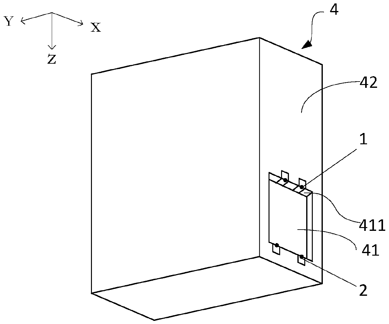
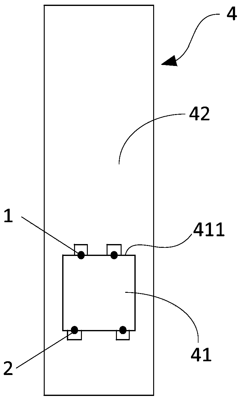
The invention relates to the field of print imaging, in particular to an imaging cartridge and a chip applied to the imaging cartridge. The imaging cartridge is detachably connected to an image forming device. Specifically, the imaging cartridge comprises a cartridge body, a first terminal and a second terminal. At least one first positioning cavity is formed in the first surface of the cartridgebody. An opening of each first positioning cavity and the first surface form a first edge. At least a portion of the first terminal and at least a portion of the second terminal are correspondingly located on the end surfaces adjacent to the first edges and / or the first edges. The first terminal is located above the second terminal in the direction in which the imaging cartridge is mounted on theimage forming device. When the imaging cartridge is mounted on the image forming device, the first positioning cavities and contact probes are constrained to each other cooperatively, and the first terminal and the second terminal are in contact with the corresponding contact probes to form a first contact portion and a second contact portion. The imaging cartridge has the beneficial effects thatthe terminals and the contact probes can be in stable electrical contact.

Description

technical field [0001] The invention relates to the field of printing and imaging, in particular to an imaging box and a chip applied to the imaging box. Background technique [0002] Replaceable printing consumables, such as toner cartridges, ink cartridges, etc., are installed in the image forming device. Printing consumables are generally equipped with chips, which can store information related to the consumables, such as ink volume information, color information, production date and so on. After the printing consumables are installed in the image forming device, the chip is electrically connected to the image forming device, and the image forming device reads the relevant information in the chip, and determines the status of the printing consumables through the information in the chip. Therefore, the stability of the electrical connection between the chip in the printing consumable and the image forming device is very important. [0003] Patent CN106864040 discloses an...

Claims


Application Information

Patent Timeline
Patent Type & Authority Applications(China)
IPC IPC(8): B41J2/175
CPCB41J2/17546B41J2/17553B41J2/1753
Inventor 刘卫臣
Owner APEX MICROELECTRONICS CO LTD
Learn More