
A calibration circuit for a wireless transceiver

A wireless transceiver and correction circuit technology, applied in electrical components, digital transmission systems, multi-carrier systems, etc., can solve the problems of wireless transceiver signal-to-noise ratio deterioration and signal mismatch, and achieve the effect of solving the signal-to-noise ratio deterioration

Active Publication Date: 2020-08-21
XIDIAN UNIV
View PDF7 Cites 0 Cited by
  • Summary
  • Abstract
  • Description
  • Claims
  • Application Information

AI Technical Summary

Problems solved by technology

[0004] However, there are also some problems in the wireless transceiver with direct frequency conversion. Among them, the signal-to-noise ratio of the wireless transceiver is severely deteriorated due to signal mismatch during transmission.

Method used


Image

  • A calibration circuit for a wireless transceiver
  • A calibration circuit for a wireless transceiver
  • A calibration circuit for a wireless transceiver

Examples


Embodiment 1

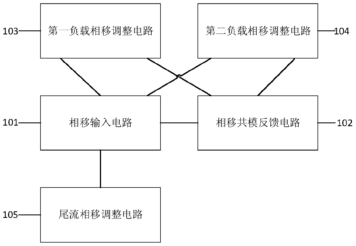
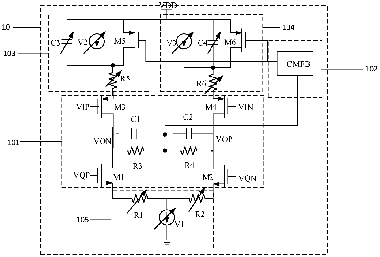
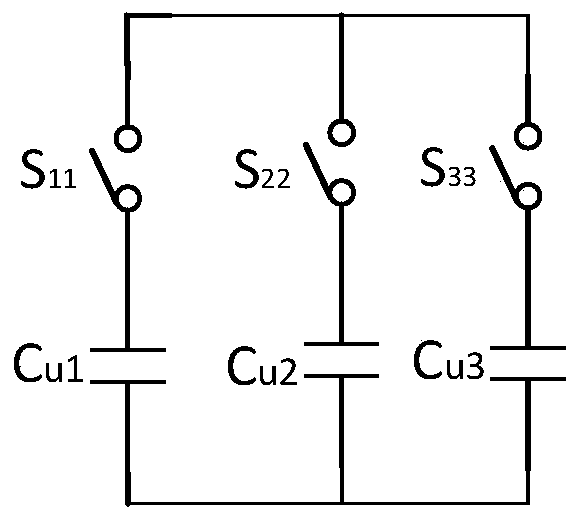
[0056] See figure 1 , figure 2 , image 3 , Figure 4 , figure 1 A schematic diagram of a circuit structure of a phase shift correction circuit provided by an embodiment of the present invention, figure 2 A schematic diagram of another circuit structure of a phase shift correction circuit provided by an embodiment of the present invention, image 3 It is a schematic circuit structure diagram of a phase-shift common-mode feedback circuit in a phase-shift correction circuit provided by an embodiment of the present invention, Figure 4 It is a schematic circuit structure diagram of a variable capacitance array in a phase shift correction circuit provided by an embodiment of the present invention. A phase shift correction circuit provided by an embodiment of the present invention, the phase shift correction circuit includes:

[0057] A phase-shift input circuit 101, configured to extract a phase-shifted differential signal from the first input signal, the second input sign...


PUM


Abstract

The invention discloses a phase shift correction circuit and a correction circuit of a wireless transceiver of the phase shift correction circuit. The phase shift correction circuit comprises a phaseshift input circuit, a phase shift common mode feedback circuit, a first load phase shift adjusting circuit, a second load phase shift adjusting circuit and a wake flow phase shift adjusting circuit.The phase shift common-mode feedback circuit is connected with the phase shift input circuit; the first load phase shift adjusting circuit is connected with the phase shift input circuit and the phaseshift common-mode feedback circuit, the second load phase shift adjusting circuit is connected with the phase shift input circuit and the phase shift common-mode feedback circuit, and the wake flow phase shift adjusting circuit is connected with the phase shift input circuit. According to the invention, phase and amplitude correction is carried out on the signal transmitted by the circuit to be corrected through the phase shift correction circuit, so that the problem of mismatch of the signal in the transmission process is solved, and the problem of deterioration of the signal-to-noise ratiocaused by mismatch is further solved.

Description

technical field [0001] The invention belongs to the field of radio frequency circuits, and in particular relates to a correction circuit of a wireless transceiver. Background technique [0002] With the increasing demand for wireless radio frequency applications and the continuous innovation of CMOS advanced manufacturing processes, wireless transceivers have put forward higher requirements for low power consumption of chips. [0003] At present, in the development process of wireless transceivers, people mostly pay attention to the circuit design of radio frequency chips, and most of the low power consumption circuits implemented in radio frequency chips are realized by digital circuits. As the functions of the wireless transceiver become more and more complex, more and more modules are integrated in the chip system, which makes the volume of the whole wireless radio frequency chip larger and larger. Among them, superheterodyne wireless transceivers are widely used transce...

Claims


Application Information

Patent Timeline
Patent Type & Authority Patents(China)
IPC IPC(8): H04L27/34H04B1/40
CPCH04B1/40H04L27/3405
Inventor 朱樟明黄胜刘术彬周荣刘帘曦郝俊艳
Owner XIDIAN UNIV
Learn More