
Bistatic MIMO radar angle estimation method based on emission energy concentration

A technology for transmitting energy and angle estimation, applied in the field of radar, can solve the problems of reducing coherent gain and angle measurement performance, and achieve the effects of reducing loss, improving angle measurement accuracy, and reducing wave departure angle error

Active Publication Date: 2019-09-03
XIDIAN UNIV
View PDF5 Cites 3 Cited by
  • Summary
  • Abstract
  • Description
  • Claims
  • Application Information

AI Technical Summary

Problems solved by technology

[0004] In the document "Angle estimation using ESPRIT in MIMO radar", a bistatic MIMO radar angle estimation method based on the ESPRIT algorithm is proposed. The echo data is solved by autocorrelation matrix and eigenvalue decomposition, so as to obtain the signal subspace containing the information of target wave departure angle and wave arrival angle; however, due to the use of completely orthogonal transmit waveforms, the transmit gain in all directions is relatively uniform , in the case of a known angular region of the target with respect to the transmitting array, actually reduces the coherence gain of the transmission and leads to a decrease in angle measurement performance, which is a significant disadvantage of conventional bistatic MIMO radar angle measurement

Method used


Image

  • Bistatic MIMO radar angle estimation method based on emission energy concentration
  • Bistatic MIMO radar angle estimation method based on emission energy concentration
  • Bistatic MIMO radar angle estimation method based on emission energy concentration

Examples


Embodiment Construction

[0030] The embodiments and effects of the present invention will be clearly and completely described below in conjunction with the accompanying drawings. Apparently, the described embodiments are only some of the embodiments of the present invention, not all of them. Based on the embodiments of the present invention, all other embodiments obtained by persons of ordinary skill in the art without making creative efforts belong to the protection scope of the present invention.

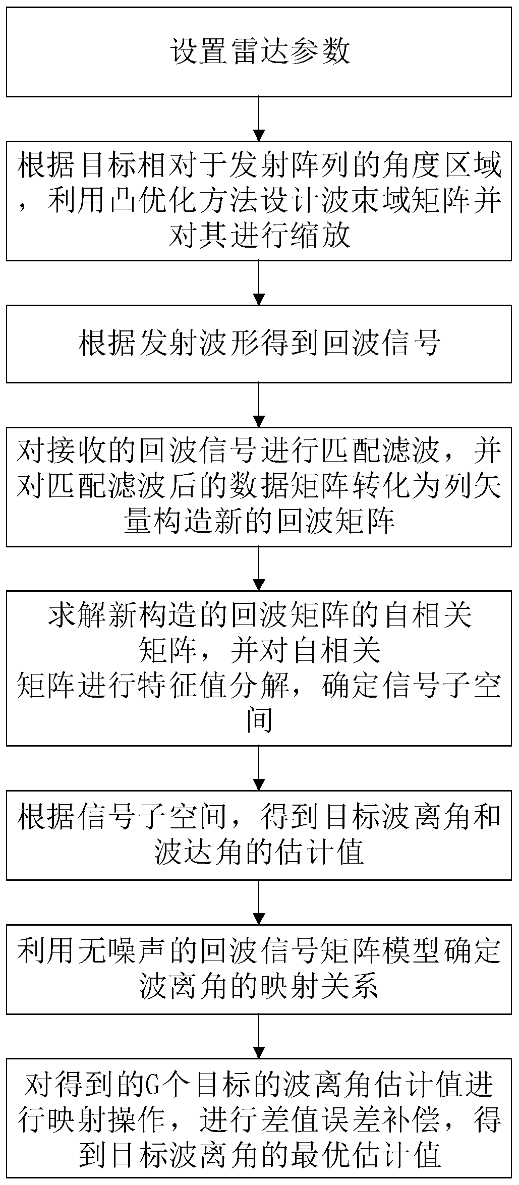
[0031] refer to figure 1 , the implementation steps of this embodiment are as follows:

[0032] Step 1, set bistatic MIMO radar parameters

[0033] Set the number of transmitting array elements of the bistatic MIMO radar as M, M>0, the number of receiving array elements as N, N>0, the total transmitting energy of the bistatic MIMO radar as E>0, and the spatial dimension of the transmitting beam domain as L, L 0;

[0034] Step 2. According to the position of the target relative to the angular area of ​​...


PUM


Abstract

The invention discloses a bistatic MIMO radar angle estimation method based on emission energy concentration. The method is realized as follows: under the condition that the angle area of the target relative to the transmitting array is known, designing a transmitting beam domain matrix by solving a convex optimization problem and zooming the matrix; defining a transmitting waveform based on a transmitting wave beam domain matrix to obtain a receiving echo model; carrying out matched filtering on the receiving echo model, and converting filtered data into a column vector to construct a new echo model; solving an autocorrelation matrix of the newly constructed echo model, and performing eigenvalue decomposition on the autocorrelation matrix to obtain a signal subspace containing wave departure angle and wave arrival angle information; obtaining estimated values of the target wave departure angle and the target wave arrival angle according to the signal subspace; and establishing a mapping relation to compensate the wave divergence angle difference error in the process of solving the convex optimization problem, so as to obtain the optimal estimated value of the target wave departureangle. The invention solves the problem of non-centralized emission energy in the prior art, improves the angle measurement precision and can be used for target detection.

Description

technical field [0001] The invention belongs to the field of radar technology, and further relates to a bistatic MIMO radar angle estimation method, which can be used to improve the problem of energy loss caused by relatively uniform transmission gains in all directions during the angle measurement process of traditional bistatic MIMO radars. Background technique [0002] Compared with traditional phased array radar, MIMO radar has attracted extensive attention in recent years. MIMO radar requires the transmitting antenna to transmit incompletely correlated waveforms on the basis of conventional phased array radar. When transmitting orthogonal waveforms, it can This makes the coverage of the signal in the airspace wider, and during signal processing, multiple beams can be formed simultaneously to cover the airspace. [0003] In bistatic MIMO radar, the wave departure angle DOD refers to the angle between the direction of the radar transmitting signal and the normal of the tr...

Claims


Application Information

Patent Timeline
Patent Type & Authority Applications(China)
IPC IPC(8): G01S7/41
CPCG01S7/41
Inventor 赵永波黄隆徐保庆
Owner XIDIAN UNIV
Learn More