
Electricity larceny prevention power distribution box

A power distribution box, anti-theft technology, applied in electrical components, panel/switch station circuit devices, substation/switch layout details, etc. Simple operation, strong practical effect

Pending Publication Date: 2019-08-30
LANGFANG POWER SUPPLY COMPANY STATE GRID JIBEI ELECTRIC POWER COMPANY +1
View PDF0 Cites 2 Cited by
  • Summary
  • Abstract
  • Description
  • Claims
  • Application Information

AI Technical Summary

Problems solved by technology

[0002] At present, the methods of stealing electricity are becoming more and more sophisticated, and the main body of stealing electricity is gradually diversified, showing the new characteristics of the combination of brutal electricity theft and intelligent electricity theft, and the intersection of small amount of electricity theft and huge amount of electricity theft, which shows that the current anti-theft electricity technology has lagged behind theft. Electric technology has affected the electricity business environment of electric power companies
[0003] Most of the existing distribution boxes are box-type structures, and the box door is usually locked and connected with the box body by a mechanical lock. The mechanical lock is easily broken and opened by man.
The meter is installed inside the box, and the meter can be accessed by opening the box door. In some areas where the supervision of the meter is not in place, this kind of distribution box is easy to be opened without authorization, the line is overlapped, and the electric energy is stolen.

Method used


Image

  • Electricity larceny prevention power distribution box
  • Electricity larceny prevention power distribution box
  • Electricity larceny prevention power distribution box

Examples


Embodiment Construction

[0027] In order to enable those skilled in the art to better understand the technical solution of the present invention, the application will be described in detail below in conjunction with the accompanying drawings. The description in this part is only exemplary and explanatory, and should not have any limiting effect on the protection scope of the application. .

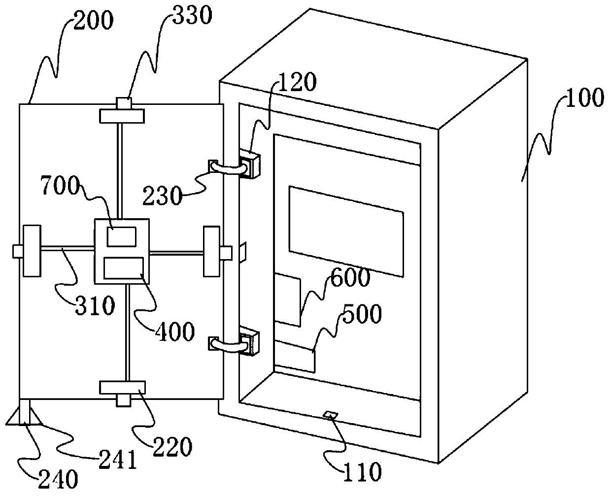
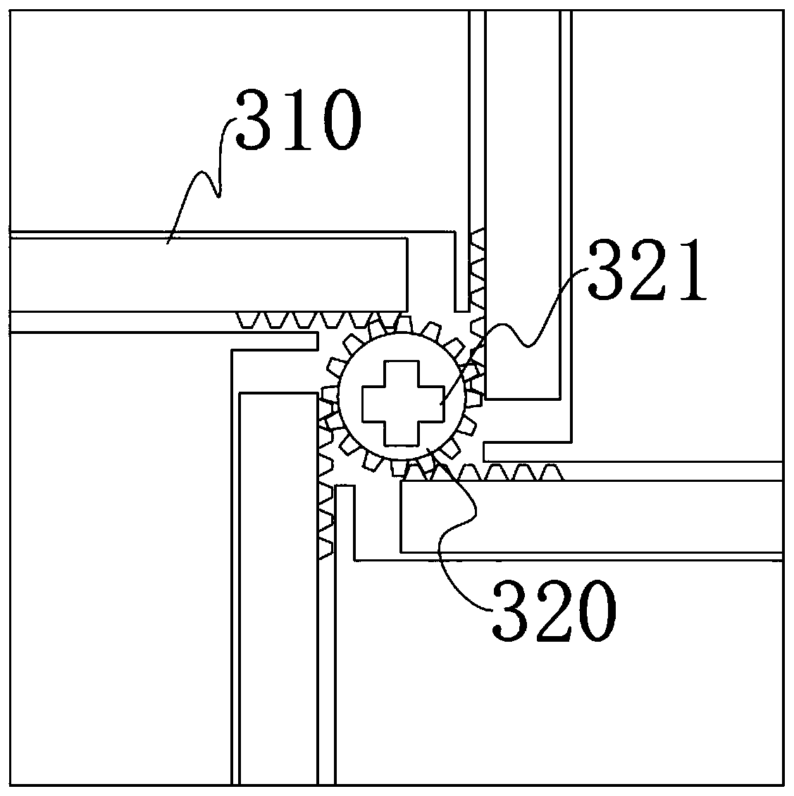
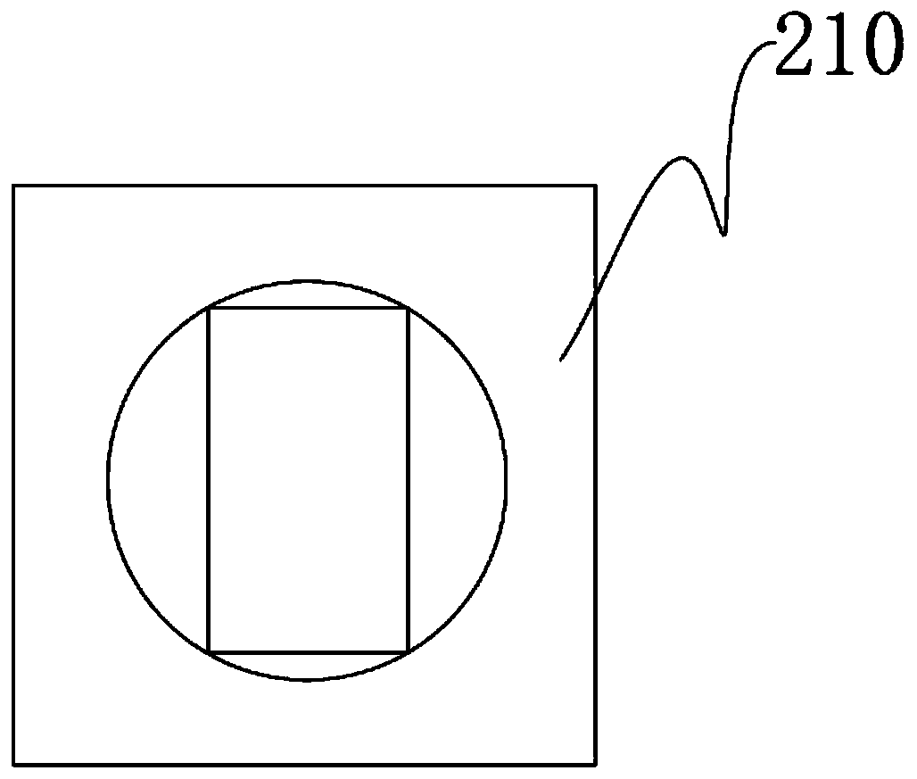
[0028] Such as figure 1 It is the first embodiment of the present application, including: a box body 100, a box door 200, and a mechanical lock arranged on the box door 200; the mechanical lock includes a cylindrical lock cylinder and a Cut four lock cylinders 310; the middle part of the box door 200 is provided with a first through hole, and the lock core is clamped on the box door 200 through the first through hole; the lock core is close to the box One end of the body 100 is provided with a gear 320, and one end of the lock cylinder 310 corresponding to the gear 320 is provided as a rack meshed with the gear 3...


PUM


Abstract

The application provides an electricity larceny prevention power distribution box comprising: a box body, a box door and a mechanical lock, wherein the mechanical lock comprises a cylindrical lock cylinder and four lock columns tangential to the outer edges of the lock cylinder; a first through hole is disposed on the center of the box door; the lock cylinder passes through the first through holeto be engaged with the box door; one end of the lock cylinder extending to the inner side of the box door is provided with a gear; one end of each lock column corresponding to the gear is provided with a rack meshed with the gear; the lock columns are disposed on the inner side of the box door; the adjacent lock columns are perpendicular to each other in the same horizontal plane; the outer side of the box door is provided with a knob corresponding to the lock cylinder; and the knob is fixedly connected to one end of the lock cylinder away from the gear; locking grooves are arranged in the boxbody corresponding to the lock columns; and an end of each lock column away from the gear is movably engaged with the locking groove. The knob on the outer side of the box door is rotated in order torotate the gear of the lock cylinder, and then screw the four locking columns tangential to the gear in or out of the locking grooves in the box body, thereby locking or unlocking the box door and the box body. The electricity larceny prevention power distribution box is easy to operate and practical.

Description

technical field [0001] The present disclosure relates to the technical field of distribution boxes, in particular to an anti-theft electricity distribution box. Background technique [0002] At present, the methods of stealing electricity are becoming more and more sophisticated, and the main body of stealing electricity is gradually diversified, showing the new characteristics of the combination of brutal electricity theft and intelligent electricity theft, and the intersection of small amount of electricity theft and huge amount of electricity theft, which shows that the current anti-theft electricity technology has lagged behind theft. Electric technology has affected the electricity business environment of electric power companies. [0003] Most of the existing distribution boxes are box-type structures, and the box door is usually locked and connected with the box body by a mechanical lock, which is easily broken and opened by man. The electric meter is installed insid...

Claims


Application Information

Patent Timeline
IPC IPC(8): H02B1/46H02B1/24E05B47/00E05C9/06E05C9/12
CPCH02B1/46H02B1/24E05B47/0012E05B47/026E05C9/06E05C9/12
Inventor 赵洪磊
Owner LANGFANG POWER SUPPLY COMPANY STATE GRID JIBEI ELECTRIC POWER COMPANY
Learn More