
An out-of-box travel switch shaft body

A travel switch and shaft technology, which is applied in the direction of electric switches, contact operating mechanisms, electrical components, etc., can solve the problems of misjudgment of the control system out of the box, output of the box signal in advance, small frictional resistance, etc., and achieve high-quality work Characteristics, optimized process, effect of low friction

Active Publication Date: 2021-11-26
GUIZHOU SPACE APPLIANCE CO LTD
View PDF6 Cites 0 Cited by
  • Summary
  • Abstract
  • Description
  • Claims
  • Application Information

AI Technical Summary

Problems solved by technology

[0004] Under normal circumstances, when the out-of-box limit switch is installed, it depends on the docking installation of its shell flange and the interface of the whole machine. At this time, it is necessary to comprehensively consider the precise position of the out-of-box chute and the installation interface of the shell flange, and must ensure that the out-of-box direction is parallel to the guide wheel. Orientation rotation direction, make the contact pair of the guide wheel and the out-of-box chute in rolling contact to obtain the minimum frictional resistance; otherwise, if the guide wheel deflects at a certain angle relative to the chute during the out-of-box process, the guide wheel will contact the out-of-box chute The pair is a sliding contact, and the frictional resistance increases sharply. In serious cases, the shaft body breaks from the threaded connection or the guide wheel 2 shears and breaks the shaft 3 and falls off. The out-of-box signal is output in advance, resulting in misjudgment of the out-of-box by the control system

Method used


Image

  • An out-of-box travel switch shaft body
  • An out-of-box travel switch shaft body
  • An out-of-box travel switch shaft body

Examples


Embodiment Construction

[0024] The technical solution of the present invention is further described below, but the scope of protection is not limited to the description.

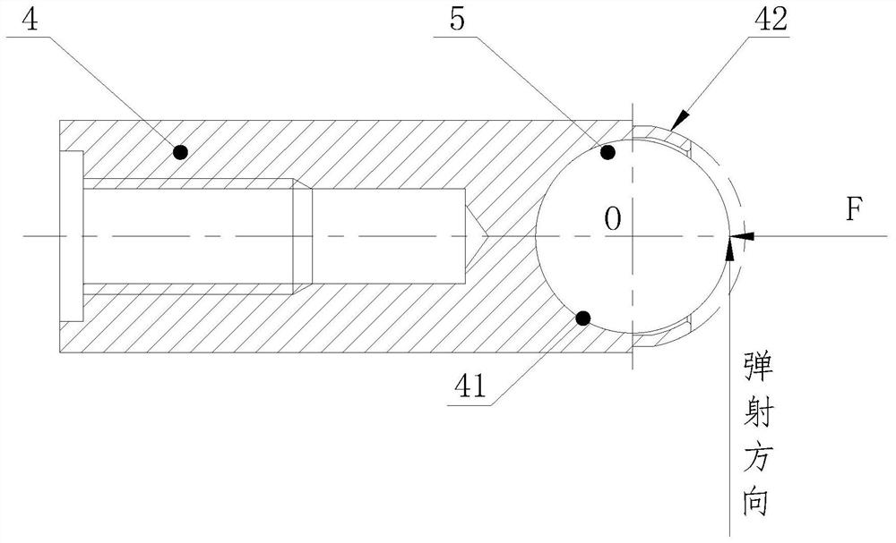
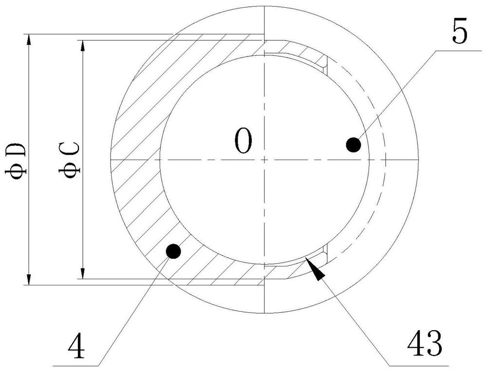
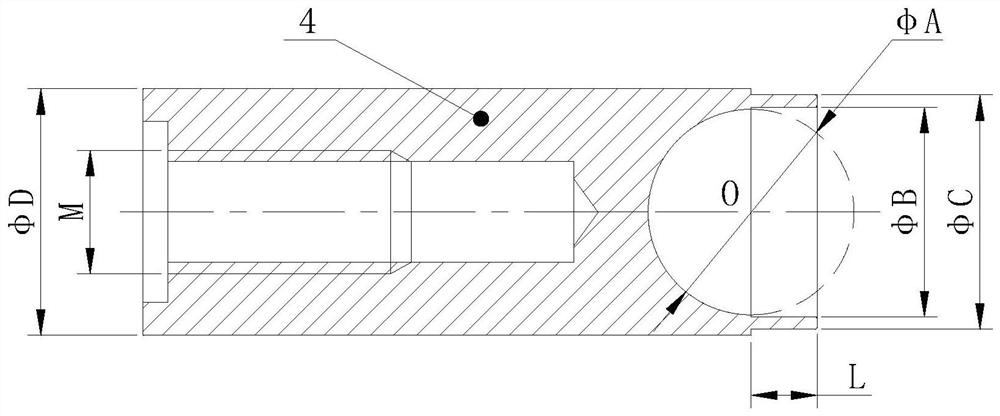
[0025] like Figure 1-3 As shown, an out-of-box limit switch shaft body includes a shaft body 4 and a steel ball 5. The shaft body 4 is a cylinder, and the bottom end of the shaft body 4 is a "U" cavity structure, which consists of a hemisphere with a diameter of φA surface 41 and a circular hole section 42 with an inner diameter of φB and a depth of L; the steel ball 5 is placed in the hemispherical surface 41, and the circular hole section 42 shrinks and locks the steel ball 5 to realize the three-axis limit of the steel ball 5. The steel ball 5 can roll at any angle within 360 degrees in the hemispherical surface 41 . The steel ball 5 rolls at any angle within 360 degrees in the hemispherical surface 41, which can realize the rolling and guiding installation at any angle during the final assembly, so that the friction force of ...


PUM


Abstract

An out-of-box limit switch shaft body, including a shaft body and a steel ball, the shaft body is a cylinder, and the bottom end of the shaft body is a "U" cavity structure, which is composed of a hemispherical surface and a circular hole section; the steel ball is placed In the hemispherical surface, the round hole section locks the steel ball necking, realizing the three-axis limit of the steel ball, so that the steel ball can roll at any angle within 360 degrees in the hemispherical surface. The invention uses the shaft and the steel ball necking The fixed rolling contact pair can be installed at any angle and guide rolling at an angle of 360 degrees, which simplifies the installation structure design of the whole machine and optimizes the process, so as to ensure the reliable output of the out-of-box travel switch signal, and ensure that the steel ball is in any angle and out of the box. The grooves form a rolling friction pair to obtain the minimum friction force, which greatly reduces the difficulty of designing the installation interface of the whole machine, ensures reliable output of the out-of-box signal, and achieves high-quality working characteristics. In addition, the technical solution of the present invention is easy to implement and can be used in various needs It is used when the travel switch is used for control.

Description

technical field [0001] The invention belongs to the field of switch control elements, and in particular relates to a shaft body of a box-out stroke switch. Background technique [0002] With the continuous improvement of the reliability requirements of modern control systems, the control system is required to give accurate and reliable synchronous out-of-box signals at the moment the system is out of the box, so that the command system can accurately identify the command status of the control system and provide a basis for judgment. As the out-of-box limit switch that provides the out-of-box signal for the control system, the success or failure of its work directly determines the success or failure of the control system to perform tasks. As the core key component of the external force transmission mechanism of the out-of-box travel switch, the shaft body is used to receive external pressure and compress the movement of the contact system to realize the on or off of the out-o...

Claims


Application Information

Patent Timeline
Patent Type & Authority Patents(China)
IPC IPC(8): H01H3/00
CPCH01H3/00
Inventor 李贤富明欢闵安蓉
Owner GUIZHOU SPACE APPLIANCE CO LTD
Learn More