
Online sidelobe suppression method and system for ultra-wideband step frequency MIMO radar

A technology of sidelobe suppression and stepped frequency, which is applied in the direction of radio wave measurement system, radio wave reflection/reradiation, instruments, etc., can solve the problems of strong influence of weak targets, lower image quality, poor resolution, etc., to achieve The effect of suppressing side lobes, improving image quality, preserving and sharpening the main lobe

Active Publication Date: 2019-08-30
HUNAN TAIKANG ELECTRONICS INFORMATION TECH CO LTD
View PDF5 Cites 2 Cited by
  • Summary
  • Abstract
  • Description
  • Claims
  • Application Information

AI Technical Summary

Problems solved by technology

The high-resolution property helps to identify the target contour features and target characteristics in the radar image, and can achieve accurate target positioning, tracking, detection and identification, but the side lobes of the radar image have a greater impact on the weak targets around the strong target, and the pulse compression The final output signal has undesired distance side lobes. Too high side lobes can easily make strong scattering points cover weak scattering points, resulting in more artifacts, poor resolution, and reduced contrast. These seriously reduce the image quality. Therefore, It is necessary to suppress the range sidelobe and improve the image quality of radar imaging

Method used


Image

  • Online sidelobe suppression method and system for ultra-wideband step frequency MIMO radar
  • Online sidelobe suppression method and system for ultra-wideband step frequency MIMO radar
  • Online sidelobe suppression method and system for ultra-wideband step frequency MIMO radar

Examples


Embodiment Construction

[0037]In order to enable those skilled in the art to better understand the technical solution of the present invention, the present invention will be described in further detail below in conjunction with the accompanying drawings and specific embodiments. And the features in the embodiments can be combined with each other.

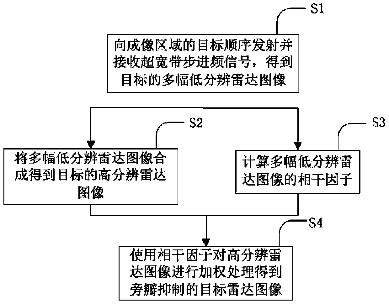
[0038] Such as figure 1 As shown, the embodiment of the present invention provides an online sidelobe suppression method for an ultra-wideband stepped frequency MIMO radar, comprising the following steps:

[0039] S1. Use the radar antenna to transmit an ultra-wideband stepping frequency signal to the imaging area where the target to be imaged is located to irradiate the target, and receive the ultra-wideband stepping frequency echo signal scattered by the irradiated target, and obtain the ultra-wideband stepping frequency part of the channel through the division operation , partial frequency band echo signals, and direct frequency-domain imaging of the e...


PUM


Abstract

The invention discloses an online sidelobe suppression method and system for an ultra-wideband step frequency MIMO radar. The method comprises the following steps: S1, sequentially transmitting and receiving ultra-wideband step frequency signals to a target in an imaging area, obtaining partial channel and partial frequency band echo signals through a division operation, and performing direct frequency domain imaging to obtain a plurality of low-resolution radar images with different characteristics of the target; S2, sequentially storing the plurality of low-resolution radar images obtained in S1, and synthesizing the plurality of low-resolution radar images to obtain a high-resolution radar image of the target; S3, calculating coherence factors of the plurality of low-resolution radar images; and S4, weighting a high-resolution radar image by using the coherence factor to obtain a target radar image after sidelobe suppression. According to the online sidelobe suppression method and system for the ultra-wideband step frequency MIMO radar, the target point of the ultra-wideband radar image is enhanced, the sidelobe and the noise point are weakened, the main lobe can be effectivelyreserved and sharpened, the sidelobe is suppressed, the sidelobe suppression is completed while the radar imaging is carried out, and the image quality of the radar images is effectively improved.

Description

technical field [0001] The invention belongs to the technical field of radar imaging, and in particular relates to an online sidelobe suppression method and system for an ultra-wideband stepped frequency MIMO radar. Background technique [0002] Multiple input multiple output (MIMO) radar is a new radar system that introduces the multiple input and multiple output technology in the wireless communication system into the radar field and combines it with digital array technology. Due to the use of waveform diversity technology, MIMO radar has many advantages that traditional phased array radars cannot match in terms of resolution, target detection performance, and target parameter estimation performance. It usually includes multiple transmitting antennas and multiple receiving antennas (antennas can also be shared by sending and receiving). The antennas are arranged according to certain rules to form an antenna array. The independent units of the antenna array are called array...

Claims


Application Information

Patent Timeline
IPC IPC(8): G01S7/28G01S13/02G01S13/89
CPCG01S7/2813G01S13/89G01S13/0209
Inventor 朱国富李志
Owner HUNAN TAIKANG ELECTRONICS INFORMATION TECH CO LTD
Learn More