Rolling bearing installation structure capable of achieving axial undamaged assembly and disassembly

A technology of rolling bearing and mounting structure, which is applied to the components of pumping device for elastic fluid, machine/engine, liquid fuel engine, etc., can solve the problem of not being able to set the axial positioning of rolling bearing to balance its own thrust, etc., and achieve convenient disassembly and assembly. Effect

Pending Publication Date: 2019-08-30
SHANGHAI MARINE EQUIP RES INST
View PDF0 Cites 2 Cited by
  • Summary
  • Abstract
  • Description
  • Claims
  • Application Information

AI Technical Summary

Problems solved by technology

[0005] The technical problem to be solved by the present invention is to propose a rolling bearing installation structure that can be assembled and disassembled axially without damage, replacing the conventional assembly structure of the rolling bearing and the rotor. Due to installation and maintenance requirements, rolling bearings cannot be installed at the extension end of the outer shaft to perform axial positioning and balance its own thrust.

Method used


Image

  • Rolling bearing installation structure capable of achieving axial undamaged assembly and disassembly
  • Rolling bearing installation structure capable of achieving axial undamaged assembly and disassembly
  • Rolling bearing installation structure capable of achieving axial undamaged assembly and disassembly

Examples


Embodiment Construction

[0019] The present invention will be further described below in conjunction with the accompanying drawings and embodiments.

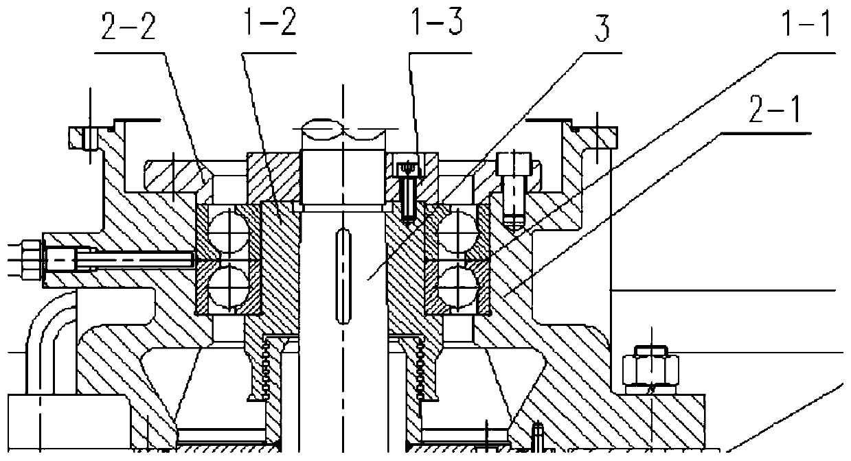
[0020] Such as image 3 As shown, a rolling bearing installation structure that can be assembled and disassembled axially without damage includes a pump shaft 3, a rolling bearing 1-1, a tapered bushing 1-2, an axial positioning nut 1-3, a bearing seat 2-1, a bearing pressure Cover 2-2.

[0021] The front part of the pump rotating shaft 3 has a tapered shaft extension, and the extended end of the tapered shaft extension is processed with threads. The rolling bearing 1-1 is first set on the tapered shaft sleeve 1-2, and the inner hole of the rolling bearing 1-1 is interference-fitted with the outer cylindrical surface of the tapered shaft sleeve 1-2. The inner hole of the tapered bushing 1-2 is a tapered hole, the assembly of the rolling bearing 1-1 and the tapered bushing 1-2 is inserted into the tapered shaft extension of the pump shaft 3, and then s...


PUM


Abstract

The invention relates to a rolling bearing installation structure capable of achieving axial undamaged assembly and disassembly. A conical shaft extension portion is arranged on the front portion of arotating shaft, and threads are formed in the outward extension end of the conical shaft extension portion. An inner ring of a rolling bearing is connected with the conical shaft extension portion onthe front portion of the rotating shaft in a cooperative mode through a conical shaft sleeve, and an outer ring of the rolling bearing is connected with an inner hole of a bearing pedestal in a cooperative mode. An inner hole of the inner ring of the rolling bearing and the outer cylindrical face of the conical shaft sleeve are in interference connection, and the outer cylindrical face of the outer ring of the rolling bearing and the inner hole of the bearing pedestal are connected in a clearance or transition fit mode. An inner hole of the conical shaft sleeve is a conical hole, and the conical hole of the conical shaft sleeve and the conical shaft extension portion on the front portion of the rotating shaft are matched with each other. The outward extension end of the conical shaft extension portion is connected with an axial locating nut through the threads. The rolling bearing installation structure capable of achieving axial undamaged assembly and disassembly can replace a conventional rolling bearing and rotor assembling structure, and can solve the technical problem that when mechanical sealing of a pump which adopts the mechanical sealing is conducted, a rolling bearing cannot be arranged at the outer shaft extension end to conduct axial locating and balance the thrust of the pump, and therefore the pump rotating shaft can be connected with a driving shaft through a flexible coupling, and the running state of a shaft system is greatly improved.

Description

technical field [0001] The invention relates to a ship pump shaft system structure, in particular to a rolling bearing installation structure in the ship pump shaft system. Background technique [0002] Rolling bearings are widely used in rotary machinery shafting. The general installation form of the rolling bearing of the rotary machinery shaft is that the inner diameter of the bearing 5 and the outer diameter of the rotating shaft 6 adopt an interference fit, and the outer diameter of the bearing 5 and the inner diameter of the bearing housing 7 adopt a clearance or transition fit. Such as figure 1 As shown, this conventional installation form can meet the stable and reliable use requirements of the shaft system, but there are also problems that the bearing is not easy to assemble and disassemble, and the assembly and disassembly process may easily lead to bearing failure. [0003] For pump machinery using mechanical seals, mechanical seals are vulnerable parts, and the...

Claims


Application Information

Patent Timeline
Patent Type & Authority Applications(China)
IPC IPC(8): F04D29/046F04D29/041F04D29/044F04D29/04F04D29/60
CPCF04D29/04F04D29/041F04D29/044F04D29/046F04D29/605
Inventor 周振东龚卫锋许宇健王东华李兵
Owner SHANGHAI MARINE EQUIP RES INST
Why Eureka
Try Eureka