Generator rotor structure and generator

A technology for generator rotors and generators, applied in electrical components, electromechanical devices, electric components, etc., can solve problems such as the inability to replace the coil frame, the difficulty in welding the balance block, and the inability to realize the balance adjustment of the unit, so as to reduce the residual unbalance, The effect of reducing vibration noise and improving performance

Pending Publication Date: 2018-04-13
湖南湘电动力有限公司
View PDF0 Cites 1 Cited by
  • Summary
  • Abstract
  • Description
  • Claims
  • Application Information

AI Technical Summary

Problems solved by technology

[0002] For large generators, the dynamic balance of the rotor is very critical. At present, it is generally adopted to install a balance block on the fan impeller at the shaft extension end of the generator, and the non-shaft extension end, that is, the exciter end, is on the main pole rotor coil frame close to the exciter rotor. The balance slot is opened, and the dynamic balance adjustment is realized by installing a balance block on the balance slot and welding the balance block firmly in the balance slot. Since the outer diameter of the main pole rotor coil frame is small, the opened balance slot is relatively small. And because it is close to the main pole coil, it is difficult to weld the balance weight. In particular, this structure cannot realize the balance adjustment of the unit during on-site commissioning because the coil frame cannot be replaced.

Method used


Image

  • Generator rotor structure and generator
  • Generator rotor structure and generator
  • Generator rotor structure and generator

Examples


Embodiment Construction

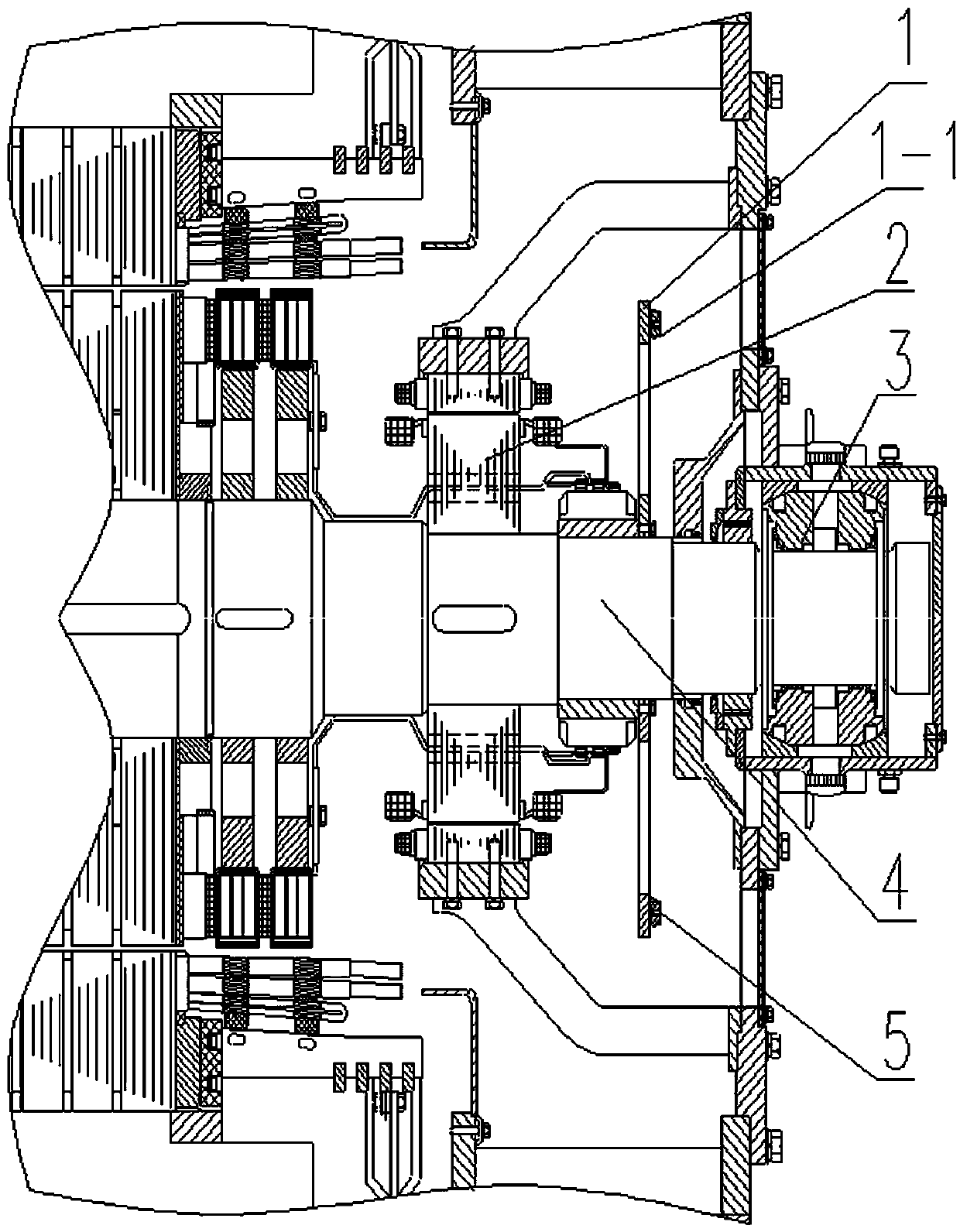
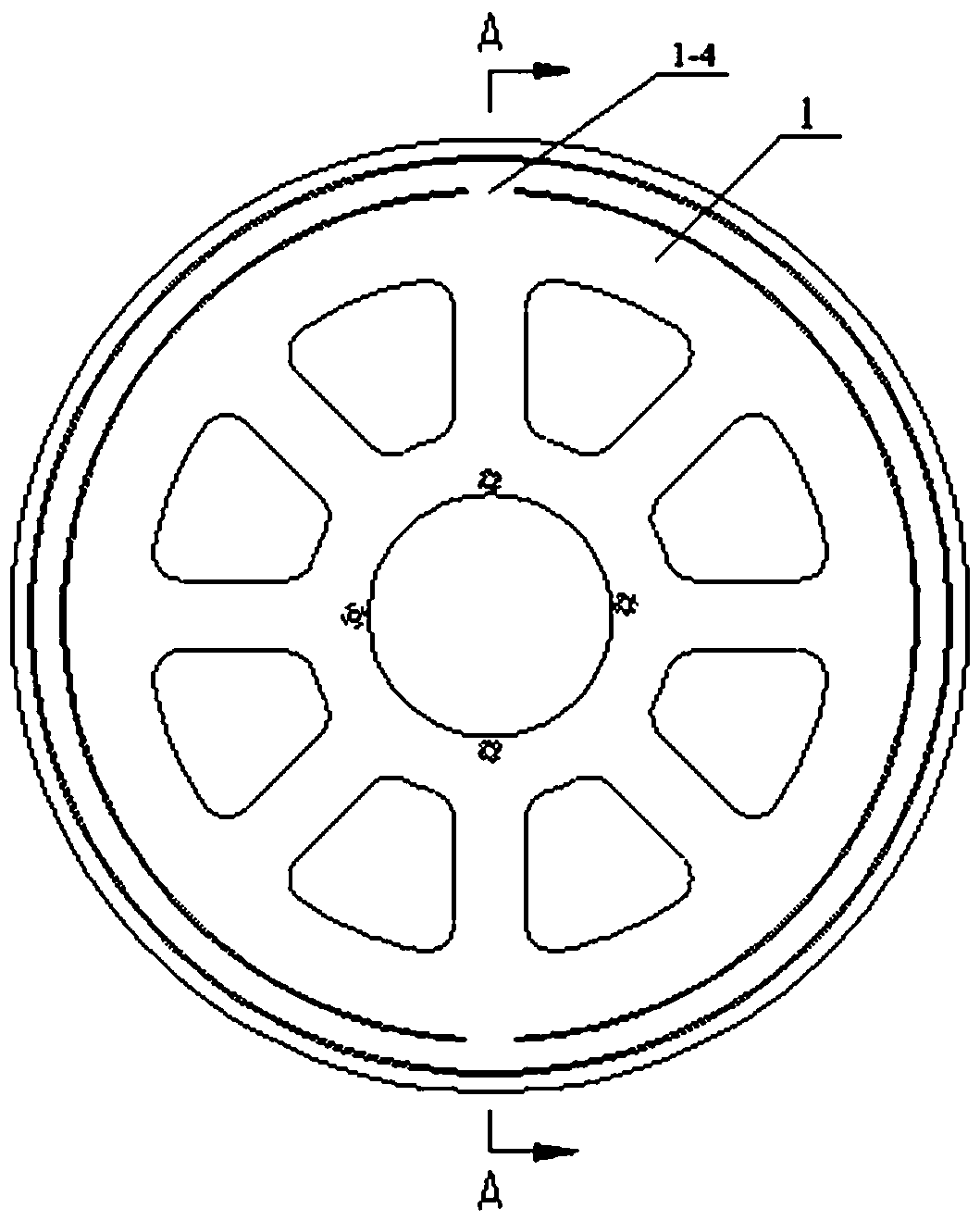
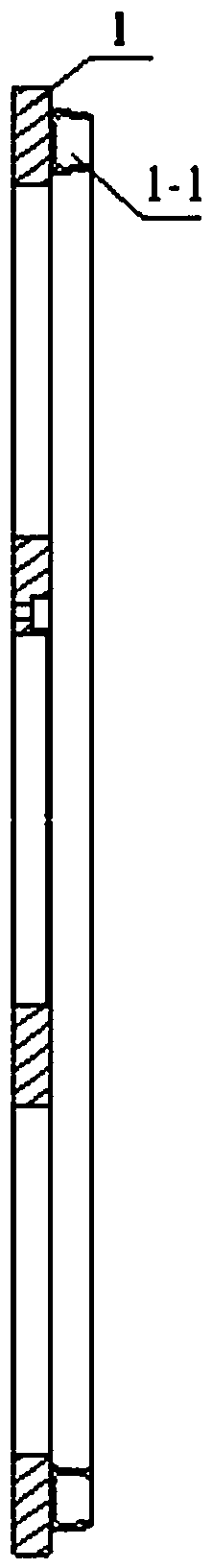
[0018] The present invention will be further described below in conjunction with the accompanying drawings and specific embodiments.

[0019] Referring to the accompanying drawings, a generator rotor structure includes a balance disc 1, the balance disc 1 is arranged between the generator exciter rotor 2 and the non-shaft end bearing 3 and fixed on the generator shaft 4, the balance disc 1 A balance groove 1-1 is provided on the disk 1, and the opening of the balance groove 1-1 faces the non-shaft end bearing 3. According to the needs of dynamic balance, a balance weight 5 is fixed at a matching position in the balance groove 1-1. In order to facilitate on-site adjustment, the outer diameter of the balance plate 1 is larger than the outer circle of the generator rotor. In order to reduce the weight, the balance plate 1 is provided with weight-reducing holes. The cross-section of the groove is a trapezoidal shape with a small outside and a big inside. In order to ensure that th...


PUM


Abstract

The invention relates to a generator rotor structure, which includes a balance plate, the balance plate is arranged between the generator exciter rotor and the non-shaft end bearing and fixed on the generator shaft, and the balance plate is provided with a balance groove , the opening of the balance groove faces the non-shaft extension bearing, the balance groove is provided with an entrance for placing a balance weight, and according to the needs of dynamic balance, a balance weight is fixed at a matching position in the balance groove. In the present invention, since the balance plate is installed on the outside of the non-shaft extension of the generator, it does not affect the maintainability and operability of the generator; by adjusting the size and weight of the balance block in the balance tank, the dynamic balance of the generator rotor is detected and adjusted on site, reducing the The residual unbalance of the generator reduces the vibration and noise of the generator and improves the vibration and noise reduction performance of the unit. The invention also relates to a generator comprising such a generator rotor structure.

Description

technical field [0001] The invention relates to the field of motors, in particular to a generator rotor structure and a generator. Background technique [0002] For large generators, the dynamic balance of the rotor is very critical. At present, it is generally adopted to install a balance block on the fan impeller at the shaft extension end of the generator, and the non-shaft extension end, that is, the exciter end, is on the main pole rotor coil frame close to the exciter rotor. The balance slot is opened, and the dynamic balance adjustment is realized by installing a balance block on the balance slot and welding the balance block firmly in the balance slot. Since the outer diameter of the main pole rotor coil frame is small, the opened balance slot is relatively small. And because it is close to the main pole coil, it is difficult to weld the balance weight. In particular, because the coil frame cannot be replaced in this structure, it is impossible to realize the balance...

Claims


Application Information

Patent Timeline
Patent Type & Authority Applications(China)
IPC IPC(8): H02K7/04
CPCH02K7/04
Inventor 陈建锋李纯清郁永涛张俊李中巍
Owner 湖南湘电动力有限公司
Why Eureka
Try Eureka