
Pneumatic tire

A technology of pneumatic tires and tires, which is applied in the direction of heavy-duty tires, off-road vehicle tires, tire parts, etc., can solve the problems of groove bottom damage and cut resistance, and achieve the effects of improved traction, sufficient cut resistance, and easy grip

Active Publication Date: 2019-08-27
THE YOKOHAMA RUBBER CO LTD
View PDF21 Cites 1 Cited by
  • Summary
  • Abstract
  • Description
  • Claims
  • Application Information

AI Technical Summary

Problems solved by technology

[0003] However, in such a tire, there is a problem that, since the groove area is also large in the shoulder portion, stones and / or rocks on the road surface and / or foreign matter tend to enter the groove provided in the shoulder portion, and the bottom of the groove Vulnerable to damage due to this (poor cut resistance)

Method used


Image

  • Pneumatic tire
  • Pneumatic tire
  • Pneumatic tire

Examples


Embodiment

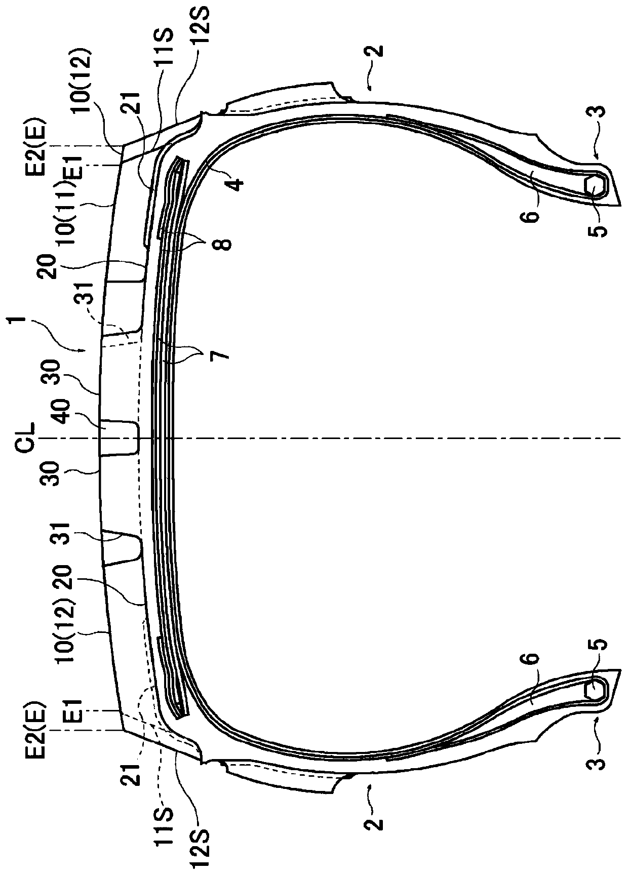
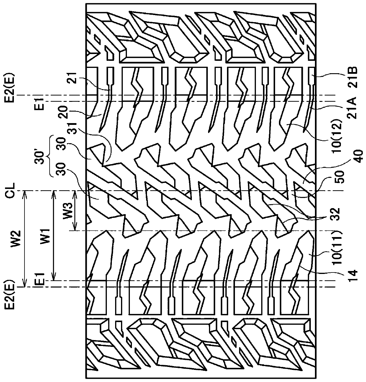
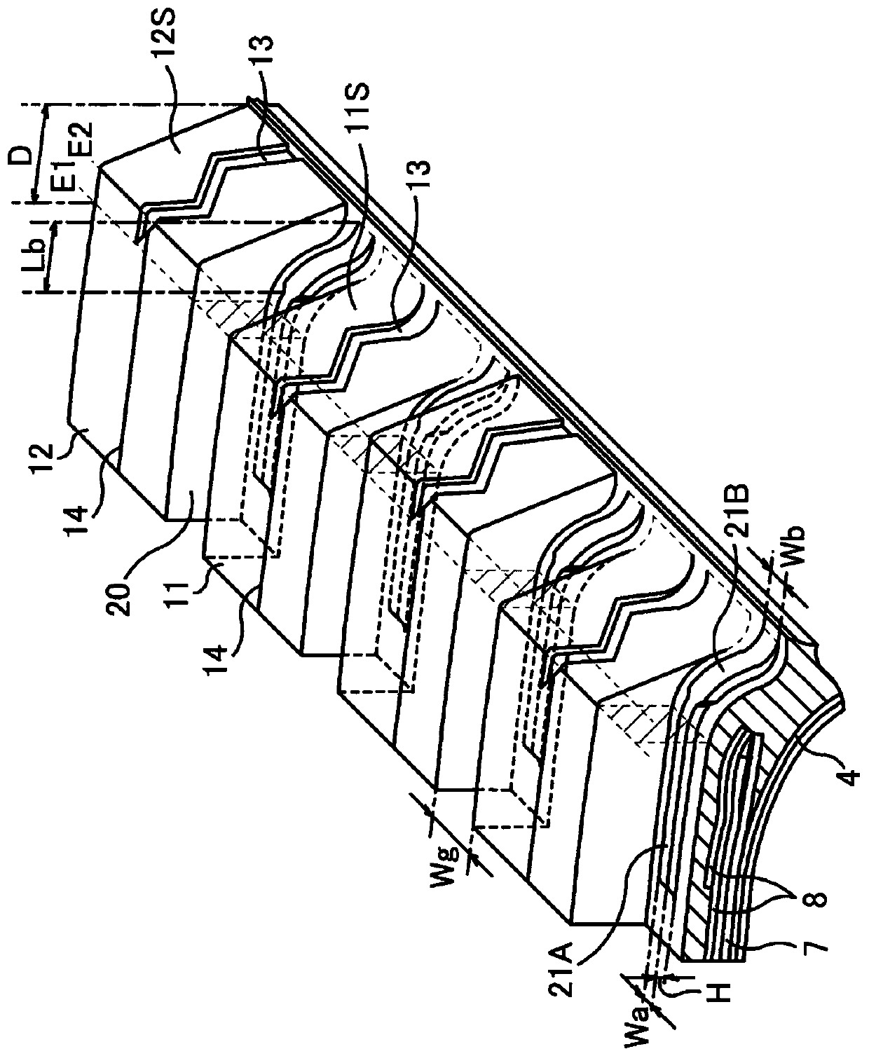
[0039] The tire size is LT265 / 70R17, with figure 1 The illustrated basic structure, with figure 2 Based on the tread pattern of the groove bottom protrusion, the shape of the groove bottom protrusion, the protrusion height H of the groove bottom protrusion, the position of the wide part of the groove bottom protrusion, and the ratio Wb of the protrusion width Wa of the wide width part of the groove bottom protrusion to the protrusion width Wb / Wa, the ratio of the tire width direction length Lb of the wide portion of the groove bottom protrusion to the distance D from the tire width direction outer end of the inner block to the end end of the outer block (Lb / D×100%), from the tire equator to The ratio of the distance W1 of the outer end in the tire width direction of the inner block to the distance W2 from the tire equator to the outer end of the outer block in the tire width direction (W1 / W2×100%) and the shape of the shallow groove are set as shown in Tables 1 and 2, respec...


PUM


Abstract

Provided is a pneumatic tire which is suitable as a tire for travelling on unpaved roads and which can achieve both high travelling performance on unpaved roads and high cut resistance. Inside blocksand outside blocks which are at different outer-end positions in the tire width direction on the tread surface are arranged alternately in the tire circumferential direction as shoulder blocks in theshoulder area of a tread portion (1). Groove bottom protrusions are arranged within the shoulder grooves between the inside blocks and the outside blocks adjacent to each other in the tire circumferential direction so as to extend beyond the outer-end positions of the inside blocks in the tire width direction from the inside to the outside in the tire width direction along the shoulder grooves. The wide-width portions of the groove bottom protrusions, which are relatively increased in width, are arranged further towards the outside in the tire width direction than the outer ends of the insideblocks in the tire width direction as seen from the front.

Description

technical field [0001] The present invention relates to a pneumatic tire suitable as a tire for running on off-paved roads, and more specifically, to a pneumatic tire capable of achieving a high balance between running performance on off-paved roads and cut resistance. Background technique [0002] Pneumatic tires used for driving on uneven, muddy, snowy, sandy, rocky, and other non-paved roads generally use tires whose tread pattern is mainly composed of horizontal grooves and / or blocks with many edge components. Pneumatic tires with large surface pattern and groove area. In such tires, traction performance is obtained by biting into mud, snow, sand, stones, rocks, etc. (hereinafter, these are collectively referred to as "mud, etc.") The running performance on non-paved roads has been improved (for example, refer to Patent Document 1). [0003] However, in such a tire, there is a problem that, since the groove area is also large in the shoulder portion, stones and / or rock...

Claims


Application Information

Patent Timeline
Patent Type & Authority Applications(China)
IPC IPC(8): B60C11/01B60C11/11B60C11/13
CPCB60C11/01B60C11/0306B60C11/1236B60C13/02B60C2011/0346B60C2011/0365B60C2011/1361B60C2200/06B60C2200/14B60C11/11B60C2011/0362
Inventor 村田尚久
Owner THE YOKOHAMA RUBBER CO LTD
Learn More