Dual wash basin water discharging device

A washbasin and water cushion technology, applied in water supply installations, indoor sanitary piping installations, buildings, etc., can solve problems such as bacterial growth, water leakage, and threat to physical health, and achieve the effect of improving the use intensity.

Pending Publication Date: 2019-08-27
台州信各灵卫浴科技有限公司
View PDF0 Cites 0 Cited by
  • Summary
  • Abstract
  • Description
  • Claims
  • Application Information

AI Technical Summary

Problems solved by technology

In the conventional sewer with the above structure, when water flows into the overflow channel 105, the water will first flow to the bottom of the gap 108 between the installation hole 104 and the sewer body 102, that is, the sealing ring 106 blocks the lower end of the installation hole 104 to form plane 109, and the overflow port 107 of the sewer main body 102 is at a higher position, then the water higher than the overflow port 107 position in the installation hole 104 can flow into the sewer, and the water below the overflow port 107 position accumulates for a long time, which is easy to cause odor, bacteria Breeding, threatening people's health
[0003] In addition, the existing sewers on the market are divided into those with overflows and those without overflows. When selecting a washbasin, it is necessary to choose a suitable washbasin according to the situation of the sewer, that is, a washbasin with an overflow channel is equipped with an overflow If the washbasin without overflow channel is matched with the drain without overflow, if the matching is not suitable, problems such as water leakage and overflow function may not be realized

Method used


Image

  • Dual wash basin water discharging device
  • Dual wash basin water discharging device
  • Dual wash basin water discharging device

Examples


Embodiment Construction

[0017] Below in conjunction with accompanying drawing and specific embodiment the present invention will be described in further detail:

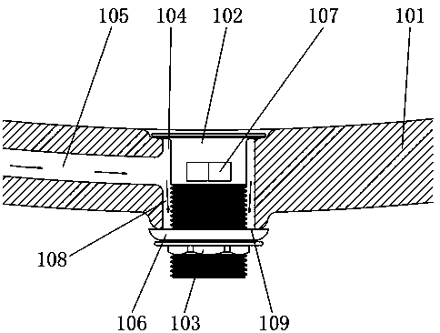
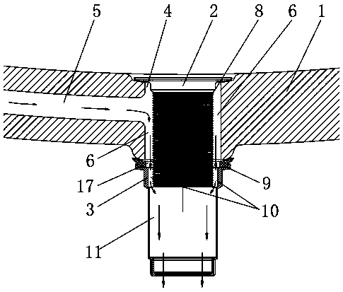
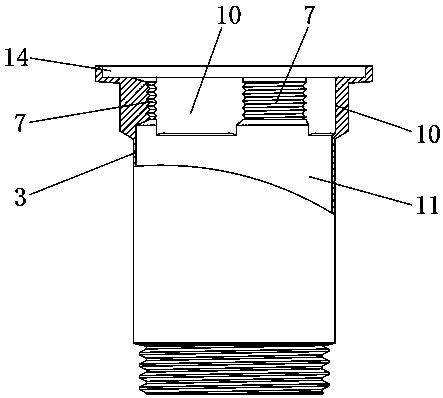
[0018] see Figure 2 to Figure 5 , the present invention provides a dual-purpose washbasin drain, comprising a washbasin 1, a sewer body 2 and a sewer connecting pipe 3, the washbasin 1 is provided with an installation hole 4 and an overflow channel 5, and the overflow channel 5 penetrates to the side wall of the installation hole 4, the water main body 2 is inserted in the installation hole 4, and a space 6 is formed between the water main body 2 and the installation hole 4, and the water connection pipe 3 is provided with an internal thread 7, The internal thread 7 is matched and screwed with the external thread 8 of the sewer main body 2, and the upper end of the sewer connecting pipe 3 is against the bottom end of the washbasin 1, and a sealing water is provided between the upper end of the sewer connecting pipe 3 and the bottom end of ...


PUM


Abstract

The invention discloses a dual wash basin water discharging device which comprises a wash basin, a water discharging body and a water discharging connecting pipe. An installation hole and an overflowrunner are installed in the wash basin. The overflow runner communicates with the side wall of the installation hole. The water discharging body is inserted in the installation hole, and an interval is formed between the water discharging body and the installation hole. An inner thread is arranged in the water discharging connecting pipe, the inner thread is matched with an outer thread of the water discharging body in a screw joint manner, and the upper end of the water discharging connecting pipe abuts against the bottom end of the wash basin. A water sealing gasket is arranged between the upper end of the water discharging connecting pipe and the bottom end of the wash basin, multiple water guide grooves are evenly distributed in the inner thread of the water discharging connecting pipein the circumferential direction. The water sealing gasket is provided with an inner hole, and a water overflow runner is commonly formed by the overflow runner, the interval, the inner hole, the multiple water guide grooves and the water discharging hole. By means of the dual wash basin water discharging device, water can be prevented from being accumulated in the overflow runner and the installation hole of the wash basin, smelliness and breeding of bacteria are avoided, and meanwhile the dual wash basin water discharging device can be used for wash basins of any type in the market.

Description

technical field [0001] The invention belongs to the technical field of drainage, and in particular relates to a dual-purpose washbasin drain. Background technique [0002] Water, usually installed in washbasins, bathtubs, etc., has the functions of drainage and water storage. Existing sewers such as figure 1 As shown, it includes a washbasin 101, a sewer body 102 and a nut piece 103. The washbasin 101 is provided with a mounting hole 104 and an overflow channel 105. The sewer body 102 penetrates from above the mounting hole 104 and extends to the mounting hole 104. Then, the sealing ring 106 is inserted into the lower end of the sewage main body 102, and finally the nut piece 103 is screwed to the lower end of the sewage main body 102, and the nut piece 103 is continuously rotated, so that itself is continuously along the axial direction of the sewage main body 102 Move up, finally the upper end of the nut piece 103 squeezes the sealing ring 106 and tightly against the bot...

Claims


Application Information

Patent Timeline
IPC IPC(8): E03C1/232
CPCE03C1/232Y02A30/60
Inventor 罗永刚
Owner 台州信各灵卫浴科技有限公司
Why Eureka
Try Eureka