
Conveyor used for large materials

A technology for bulk materials and conveyors, which is applied in the field of bulk materials conveyors. It can solve the problems of easy blockage of pipelines, inability to install in limited installation sites, and limited number of conveying times, so as to achieve the effect of ensuring reliability and no dust pollution.

Pending Publication Date: 2019-08-27
JINAN YULONG PNEUMATIC CONVEYING EQUIP +1
View PDF0 Cites 0 Cited by
  • Summary
  • Abstract
  • Description
  • Claims
  • Application Information

AI Technical Summary

Problems solved by technology

[0002] Powder material conveying equipment (delivery bin pump), the conveyed material is powdery or granular (particle size <30mm), if the bulk material is transported by the bin pump, the bulk material must be crushed and screened first, and those that meet the requirements The materials are concentrated and then transported by the sending warehouse pump; if the warehouse pump is used to directly transport the block material with a diameter of 30-100mm, when feeding, the valve above the warehouse pump will be closed when it reaches the material level of the warehouse pump and the feeding time When it is closed, the large material will be squeezed into the valve, causing the valve to fail to close normally; when it is closed, the pipeline is extremely easy to block during transportation; the sending warehouse pump cannot complete continuous transportation during the transportation process; The number of deliveries within a certain period of time is limited, and the higher the installation height of the sending warehouse pump, the installation cannot be installed in some limited installation sites.

Method used


Image

  • Conveyor used for large materials
  • Conveyor used for large materials
  • Conveyor used for large materials

Examples


Embodiment Construction

[0031] In order to clearly illustrate the technical features of the present solution, the present invention will be described in detail below through specific implementation methods and in conjunction with the accompanying drawings. The following disclosure provides many different embodiments or examples for implementing different structures of the present invention. To simplify the disclosure of the present invention, components and arrangements of specific examples are described below. Furthermore, the present invention may repeat reference numerals and / or letters in different instances. This repetition is for the purpose of simplicity and clarity and does not in itself indicate a relationship between the various embodiments and / or arrangements discussed. It should be noted that components illustrated in the figures are not necessarily drawn to scale. Descriptions of well-known components and processing techniques and processes are omitted herein to avoid unnecessarily lim...


PUM


Abstract

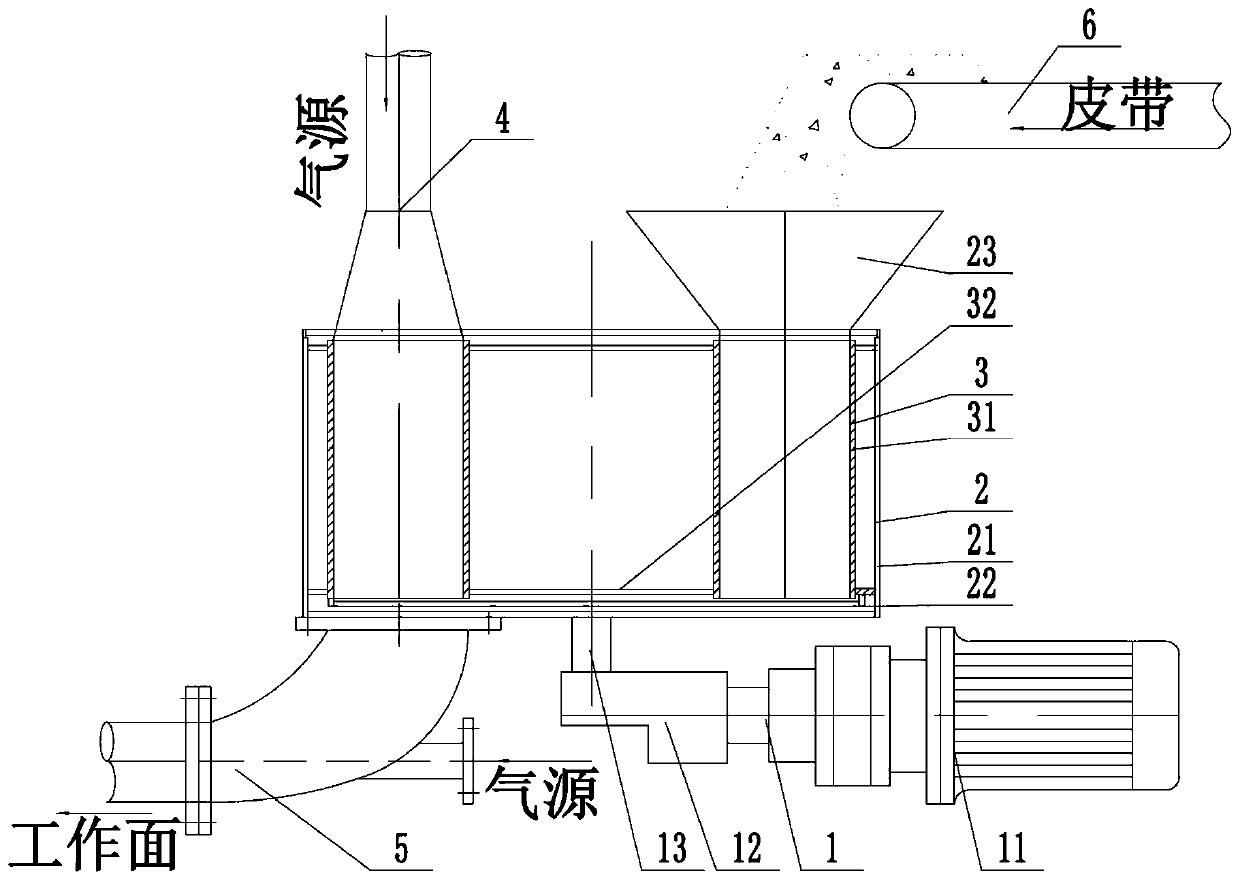
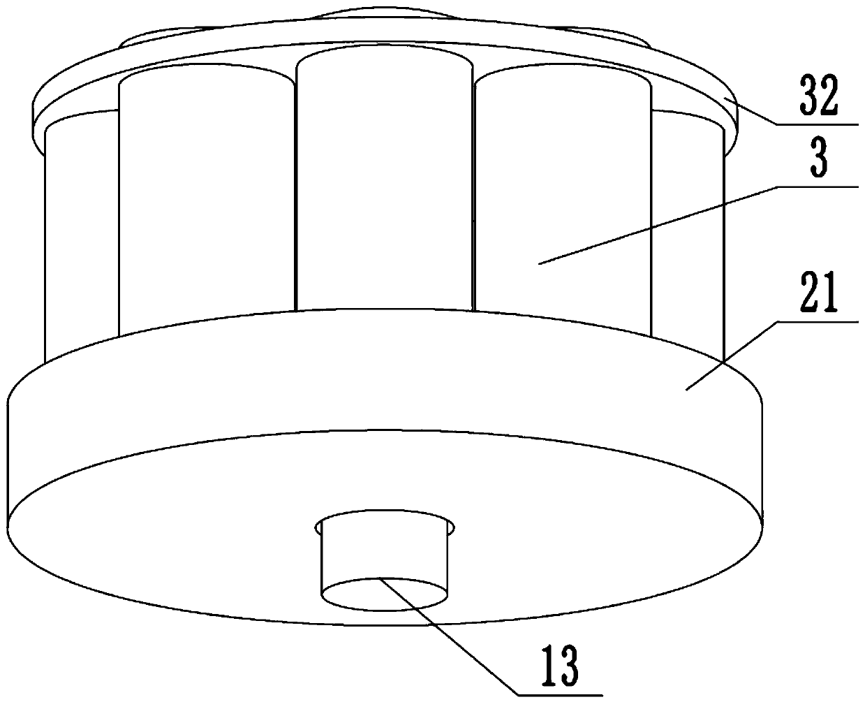
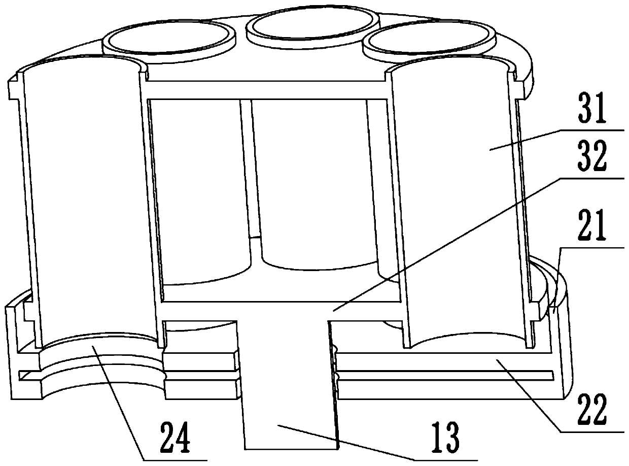
The invention discloses a conveyor used for large materials. The conveyor comprises a driving mechanism and the like. A conveying mechanism comprises a small charging barrel. The driving mechanism isconnected with the small charging barrel which is mounted in a support cylinder. A pressure ventilation pipe matched with the small charging barrel is arranged on the upper portion of the support cylinder. A mixing pipe matched with the small charging barrel for discharging is arranged in the downwind direction of the pressure ventilation pipe. The small charging barrel communicates with the pressure ventilation pipe and the mixing pipe. The mixing pipe is mounted on the lower portion of the support cylinder. A belt used for conveying large materials is arranged on the upper portion of a receiving hopper. The driving mechanism drives the small charging barrel to move in the support cylinder to reach the position below the receiving hopper, the large materials fall into the small charging barrel through the receiving hopper, the driving mechanism drives the small charging barrel full of the materials to move to the pressure ventilation pipe and the mixing pipe, the materials in the small charging barrel are blown into the mixing pipe under the effect of a high wind pressure of the pressure ventilation pipe to be mixed with gas subsequently, and in this way, the large materials are transferred through the small charging barrel; and when a plurality of small charging cylinders are arranged, materials can be continuously transferred.

Description

technical field [0001] The invention relates to the technical field of bulk material conveying, in particular to a bulk material conveyor with a diameter of 30-100 mm such as coal or coal gangue. Background technique [0002] Powder material conveying equipment (delivery bin pump), the conveyed material is powdery or granular (particle size <30mm), if the bulk material is transported by the bin pump, the bulk material must be crushed and screened first, and those that meet the requirements The material is concentrated and then transported by the sending warehouse pump; if the warehouse pump is used to directly transport the block material with a diameter of 30-100mm, when feeding, the valve above the warehouse pump is closed when it reaches the material level of the warehouse pump and the feeding time When it is closed, the large material will be squeezed into the valve, causing the valve to fail to close normally; when it is closed, the pipeline is extremely easy to bloc...

Claims


Application Information

Patent Timeline
IPC IPC(8): B65G53/34B65G53/06B65G53/40
CPCB65G53/34B65G53/06B65G53/40
Inventor 韩亮曹成郭庆
Owner JINAN YULONG PNEUMATIC CONVEYING EQUIP
Learn More