Combination method of photoelectric coupling lens

A technology of photoelectric coupling and combination method, applied in the direction of lens, optics, optical components, etc., can solve the problems of low lens polishing efficiency, time-consuming and laborious, poor lens polishing environment, etc.

Active Publication Date: 2019-08-27
九江祥明光学科技有限公司
View PDF11 Cites 1 Cited by
  • Summary
  • Abstract
  • Description
  • Claims
  • Application Information

AI Technical Summary

Problems solved by technology

[0002] At present, the combination process of the photoelectric conversion module is usually composed of multiple lenses. The lens is an important photoelectric conversion module component. During the production process of the lens, a large amount of grinding work is required for the lens. , most of the grinding devices are still controlled by people, and the grinding work of the lens is realized by holding the lens to meet the grinding wheel. In this process, it is not only time-consuming and laborious, but also has many hidden dangers, and there is a special limitation on the efficiency of lens grinding. Low, and the environment for lens grinding is also quite poor. Therefore, a time-saving, labor-saving, high-efficiency, and high-safety lens grinding device is necessary.

Method used


Image

  • Combination method of photoelectric coupling lens
  • Combination method of photoelectric coupling lens
  • Combination method of photoelectric coupling lens

Examples


Embodiment Construction

[0022] All features disclosed in this specification, or steps in all methods or processes disclosed, may be combined in any manner, except for mutually exclusive features and / or steps.

[0023] Any feature disclosed in this specification (including any appended claims, abstract and drawings), unless expressly stated otherwise, may be replaced by alternative features which are equivalent or serve a similar purpose. That is, unless expressly stated otherwise, each feature is one example only of a series of equivalent or similar features.

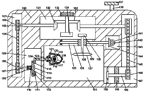
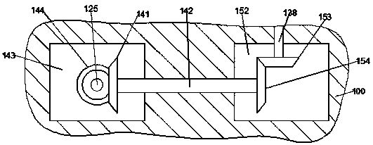
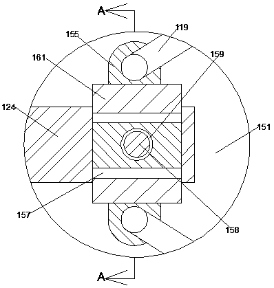
[0024] Such as Figure 1-4As shown, a combination method of a photoelectric coupling lens of the device of the present invention includes a polishing box 100 and a polishing cavity 151 that is opened forward in the polishing box 100, and the upper end of the polishing cavity 151 is provided with a driving cavity 131 The left and right ends of the driving chamber 131 are provided with a symmetrical transmission chamber 101 extending up and dow...


PUM


Abstract

The present invention discloses a combination method of a photoelectric coupling lens; the photoelectric coupling lens includes a grinding box body, and a grinding chamber that is disposed in the grinding box body and opened forward; an upper end of the grinding chamber is provided with an actuating chamber, left and right ends of the actuating chamber are provided with symmetrical transmission chambers extending upward and downward, sliding grooves extending left and right are disposed between the actuating chamber and the grinding chamber in a communication manner, and a dust suction chamberthat communicates with the transmission chamber at the right end and extends left and right is disposed at a right end of the grinding chamber in a communication manner; a control device is disposedbetween the transmission chamber at the right end and the sliding groove, wherein an actuating device is disposed in the actuating chamber, a transmission shaft is disposed between the actuating chamber and the transmission chamber, a transmission mechanism connected to the actuating device through the transmission shaft is disposed in the transmission chamber, and an oscillation chamber is disposed at a left end of the grinding chamber; the photoelectric coupling lens of the present invention has the advantages of simple structure, convenience to use and practicability.

Description

technical field [0001] The invention relates to the technical field of photoelectric coupling lens processing, in particular to a method for combining photoelectric coupling lenses. Background technique [0002] At present, the combination process of the photoelectric conversion module is usually composed of multiple lenses. The lens is an important photoelectric conversion module component. During the production process of the lens, a large amount of grinding work is required for the lens. , most of the grinding devices are still controlled by people, and the grinding work of the lens is realized by holding the lens to meet the grinding wheel. In this process, it is not only time-consuming and laborious, but also has many hidden dangers, and there is a special limitation on the efficiency of lens grinding. Low, and the lens grinding environment is also quite poor. Therefore, it is necessary to save time and effort, work more efficiently, and have a higher safety factor for ...

Claims


Application Information

Patent Timeline
Patent Type & Authority Applications(China)
IPC IPC(8): B24B13/04B24B13/005B24B13/01B24B47/12B24B55/06
CPCB24B13/0052B24B13/01B24B13/04B24B47/12B24B55/06
Inventor 周青金慧丽
Owner 九江祥明光学科技有限公司
Why Eureka
Try Eureka