
Skin piece perforating device

A technology for hole-making devices and skin parts, which is applied in the direction of manufacturing tools, boring/drilling, drilling/drilling equipment, etc. Low position accuracy and other issues, to achieve the effect of improved efficiency, convenient adjustment, and reduced labor intensity

Pending Publication Date: 2019-08-27
UNIV OF SCI & TECH LIAONING
View PDF0 Cites 1 Cited by
  • Summary
  • Abstract
  • Description
  • Claims
  • Application Information

AI Technical Summary

Problems solved by technology

The traditional manual hole making method not only has low hole position accuracy and unstable hole quality, but also can hardly meet the requirements of enterprises in processing efficiency. At the same time, this method of hole making also has potential safety hazards. In order to improve this situation, a High-precision, high-efficiency hole making device is imperative

Method used


Image

  • Skin piece perforating device
  • Skin piece perforating device
  • Skin piece perforating device

Examples


Embodiment 1

[0045] The skin part hole-making device described in this embodiment is used for processing a certain skin part. The counterweight wheel frame weighs 16Kg, its material is LY12, and its thickness is 2mm.

[0046] In this embodiment, the hole diameter of the skin is 4.2 mm, the number of holes is 80, and the holes are distributed in 4 rows and 8 columns.

[0047] The rodless cylinder adopts the balance cylinder of SMC series, and its cylinder diameter is 30mm. The models of tensioning timing belt and timing pulley are MBQ and FTPA-MXL respectively. The horizontal guide rail and the vertical guide rail adopt HIWIN series linear guide rail respectively, the model is SSVRB.

[0048] In this embodiment, the entire hole-making process is successfully completed by using the skin-piece hole-making device of the present invention, which is easy to operate and can meet the requirements for flexible hole-making at multiple angles such as obliquely upward and obliquely downward.

Embodiment 2

[0050] The skin part hole-making device described in this embodiment is used to process a certain skin part. The counterweight wheel frame weighs 18Kg, the material is LC4, and the thickness is 3mm.

[0051] In this embodiment, the hole diameter of the skin is 5 mm, the number of holes is 120, and the holes are distributed in 6 rows and 20 columns.

[0052] The rodless cylinder adopts the balance cylinder of SMC series, and its cylinder diameter is 30mm. The models of tensioning timing belt and timing pulley are MBQ and FTPA-MXL respectively. The horizontal guide rail and the vertical guide rail adopt HIWIN series linear guide rail respectively, the model is SSVRB.

[0053] In this embodiment, the whole hole-making process is successfully completed by using the skin-piece hole-making device of the present invention, which is easy to operate and can meet the requirement for lamination of aluminum alloy and skin-piece for hole-making.


PUM

PropertyMeasurementUnit
diameteraaaaaaaaaa

Abstract

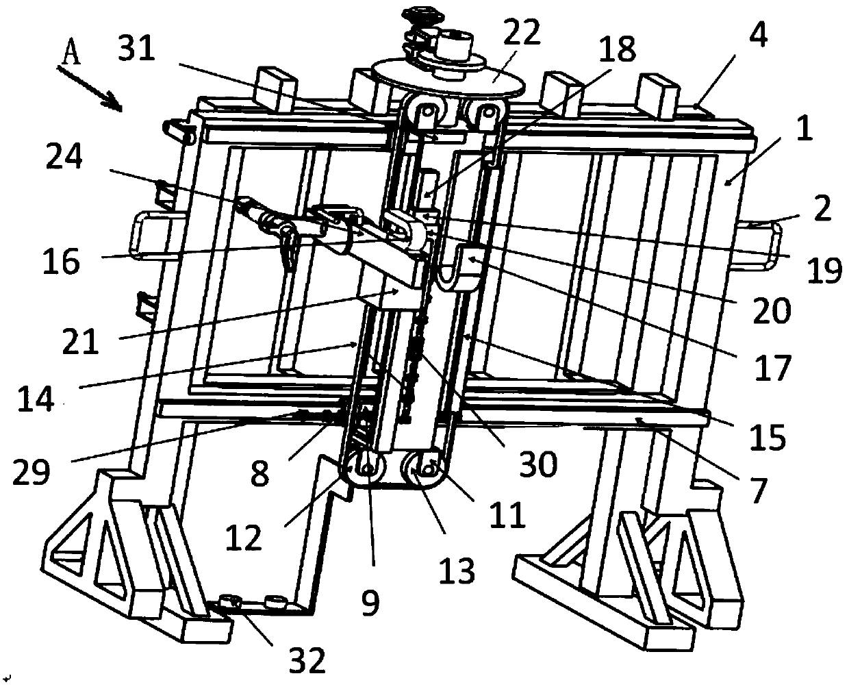
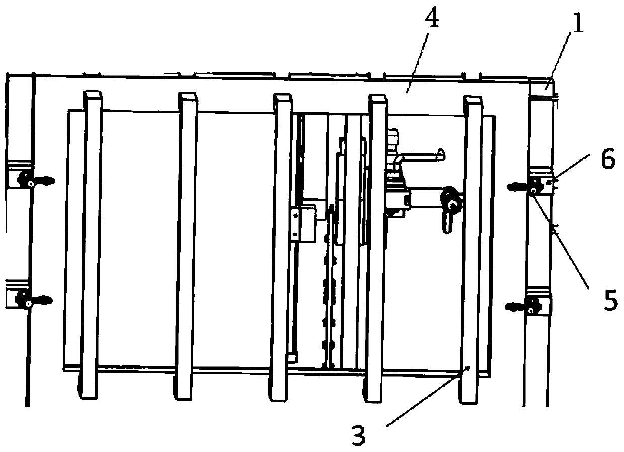
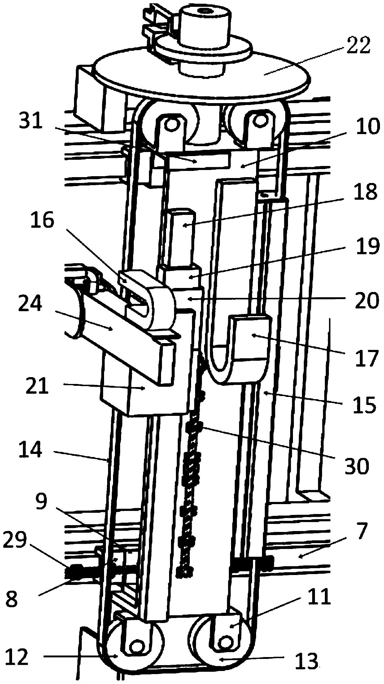
The invention relates to a skin piece perforating device. The skin piece perforating device comprises a frame, and a horizontal adjusting mechanism, a vertical adjusting mechanism, a drill fine adjustment mechanism and a drill arranged on the frame; multiple elbow clamps are arranged on one side of the frame for clamping and fixing skin pieces; the horizontal adjusting mechanism is arranged on theother side of the frame; the vertical adjusting mechanism is arranged on the horizontal adjusting mechanism, and can horizontally move in the longitudinal direction of the frame along with the horizontal adjusting mechanism; the drill fine adjusting mechanism is arranged on the vertical adjusting mechanism, and can vertically move in the height direction of the frame along with the vertical adjusting mechanism; and the drill is arranged on the drill fine adjustment mechanism, and can move in the transverse direction of the frame along with the drill fine adjustment mechanism and horizontallyswing. The skin piece perforating device is simple in structure and operation method and excellent in generality, can improve the skin piece perforating precision and efficiency, and improves the operation safety.

Description

technical field [0001] The invention relates to the technical field of skin processing, in particular to a hole-making device for skin parts. Background technique [0002] With the rapid development of aviation, aerospace and high-speed rail fields, the requirements for the manufacturing and processing quality of skin parts are getting higher and higher, which promotes the continuous development of the processing technology of skin parts. How to realize efficient and high-quality hole making has always been an important research content. The traditional manual hole making method not only has low hole position accuracy and unstable hole quality, but also can hardly meet the requirements of enterprises in processing efficiency. At the same time, this method of hole making also has potential safety hazards. In order to improve this situation, a High-precision and high-efficiency hole-making devices are imperative. Contents of the invention [0003] The invention provides a ...

Claims


Application Information

Patent Timeline
Patent Type & Authority Applications(China)
IPC IPC(8): B23B41/00
CPCB23B41/00
Inventor 焦安源陈晓梅陈福龙刘炳宏张国富王凤辉
Owner UNIV OF SCI & TECH LIAONING
Learn More