Eureka AIR delivers breakthrough ideas for toughest innovation challenges, trusted by R&D personnel around the world.

Hole making method of butt joint surface structure of large aircraft body

An aircraft fuselage and docking surface technology, applied in the field of aircraft manufacturing, can solve the problems of difficulty in ensuring the consistency of hole-making quality, inability to complete the hole-making work, and restricting aircraft production efficiency, so as to avoid hole-making quality problems and reduce tool replacement. time, the effect of reducing tool usage

Inactive Publication Date: 2019-08-27
XIAN AIRCRAFT IND GROUP
View PDF4 Cites 2 Cited by
  • Summary
  • Abstract
  • Description
  • Claims
  • Application Information

AI Technical Summary

Problems solved by technology

After the traditional manual hole making uses drawing lines to position the parts, the operator uses a vertical drill sleeve on the outside of the fuselage to penetrate the inside of the fuselage to complete the preparation of the front and rear two docking faces. This process is intensive and the quality of the hole is consistent with the hole The accuracy is not easy to guarantee, and in the process of manual hole making, different tools need to be replaced repeatedly to complete the initial hole, reaming, reaming, spot facing / chamfering, the hole making efficiency is low, which seriously restricts the production efficiency of the aircraft
[0004] Due to the circular structure of the butt joint surface of the aircraft fuselage and the large size of the aircraft, it is impossible to complete the hole making work with the existing automatic hole making equipment

Method used


Image

  • Hole making method of butt joint surface structure of large aircraft body
  • Hole making method of butt joint surface structure of large aircraft body

Examples


Embodiment Construction

[0027] The present invention will be further described below in conjunction with the accompanying drawings and embodiments.

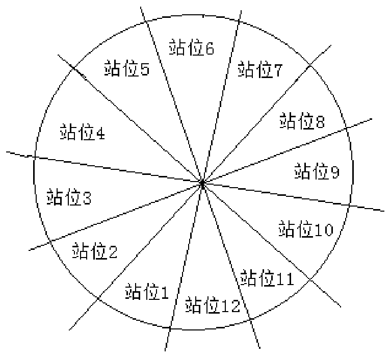
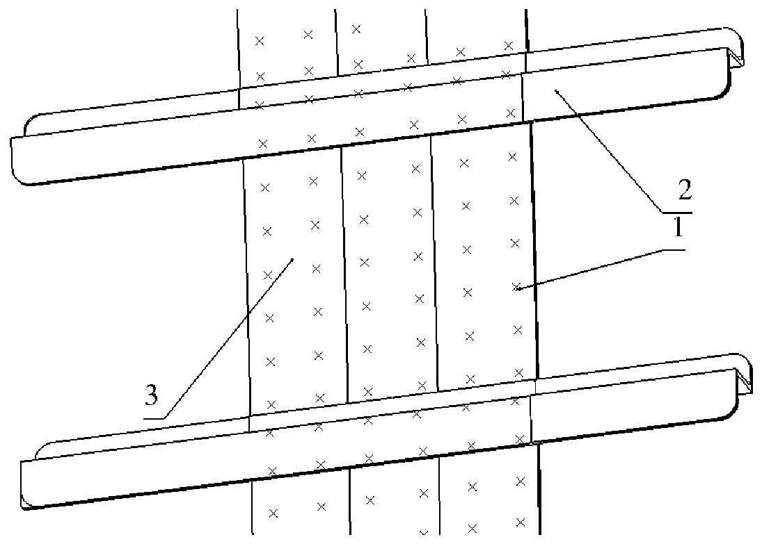
[0028] figure 1 , 2 It is an example of making holes in the structure of the docking surface of a large aircraft fuselage. The specific hole making process is as follows:

[0029] A hole-making method for the butt joint surface structure of a large aircraft fuselage, using circular rail automatic hole-making equipment to make holes for the butt joint surface structure of the aircraft fuselage. Skin, the hole making process comprises the following steps:

[0030] Step 1: Divide the theoretical model of the aircraft fuselage docking surface structure into multiple stations according to the arc length of the arc-shaped rail on the circular rail automatic hole-making equipment around the fuselage docking surface, so that each station can make a number of holes most;

[0031] Step 2: Input the theoretical hole-making position on the joint surface structu...


PUM


Abstract

The invention discloses a hole making method of a butt joint surface structure of a large aircraft body. According to the hole making method, annular rail automatic hole making equipment is used, holes are made in the butt joint surface structure of the aircraft body, an arc-shaped rail arc length on the annular rail automatic hole making equipment is divided into a plurality of station positionsaround the butt joint surface of a machine body, so that each station can have the largest number of holes, a long truss joint and a butt strap plate are arranged on the butt joint surface, process screws are installed, the position of the process screws serves as a hole making reference, and the station positions are built by using the reference hole process screws. A hole making program is corrected, and hole making and counter sinking in the station butt joint surface structure are carried out. The arc-shaped rail is rotated to the next station position until the hole making of the joint surface structure of the machine body at all stations is completed.

Description

technical field [0001] The present application relates to the technical field of aircraft manufacturing, in particular to a hole-making method for a butt joint surface structure of a large aircraft fuselage. Background technique [0002] A large part of the aircraft fuselage is docked on the process separation surface between the frames. The skin of the docking surface is a hyperboloid structure. The aircraft skin is connected. [0003] In the docking work of the fuselage, not only the quality of the holes is strictly required, but also the number of holes is huge. After the traditional manual hole making uses drawing lines to position the parts, the operator uses a vertical drill sleeve on the outside of the fuselage to penetrate the inside of the fuselage to complete the preparation of the front and rear two docking faces. This process is intensive and the quality of the hole is consistent with the hole The accuracy is not easy to guarantee, and in the process of manual ...

Claims


Application Information

Patent Timeline
Patent Type & Authority Applications(China)
IPC IPC(8): B23B35/00
CPCB23B35/00
Inventor 梁青霄邹春喜张凯李斌白云鹏
Owner XIAN AIRCRAFT IND GROUP
Why Eureka
Eureka Blog
Learn More