
Ultrasonic vibration meter

A technology of ultrasonic wave and vibration instrument, which is applied in the field of experimental equipment, can solve the problems of non-vibration of experimental vessels, poor oscillation effect, influence on oscillation and cell lysis effect, and achieve automatic opening and closing, avoiding excessive movement, and preventing stalling Effect

Pending Publication Date: 2019-08-27
AORAN BIOTECH SHANGHAI
View PDF0 Cites 0 Cited by
  • Summary
  • Abstract
  • Description
  • Claims
  • Application Information

AI Technical Summary

Problems solved by technology

[0003] However, the operator found in the actual use process that after starting the ultrasonic vibrator, the initial vibration effect is better, but the longer the time goes, the worse the vibration effect is, and even the experimental vessel does not vibrate.
After analysis, this problem is mainly due to the small displacement of the experimental vessel during the oscillation process, that is, a gap between the experimental vessel and the ultrasonic generator, which affects the oscillation and cell lysis effect

Method used


Image

  • Ultrasonic vibration meter
  • Ultrasonic vibration meter
  • Ultrasonic vibration meter

Examples


Embodiment 1

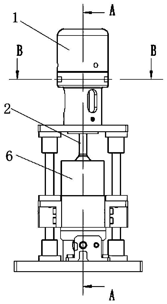
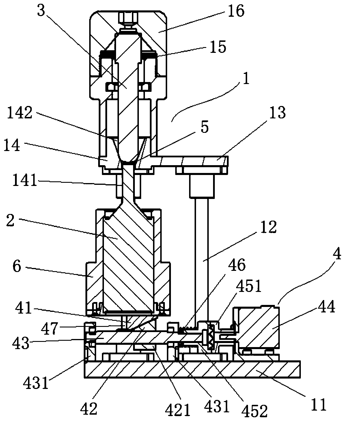
[0045] This embodiment relates to a kind of ultrasonic vibration instrument, its structure is as follows Figure 1~4 As shown, it includes a laboratory vessel fixing frame 1 and an ultrasonic generator 2 . In this embodiment, the experimental vessel 3 is a test tube. In this embodiment, the ultrasonic generator is an ultrasonic vibrator. The experimental vessel 3 is fixed in the experimental vessel holder 1, the sonotrode 2 is arranged inside the sonotrode shell 6, and the top of the sonotrode 2 abuts against the bottom end of the test vessel 3, and the bottom of the sonotrode shell 6 is arranged There is a lifting mechanism 4. In the implementation shown in this example, the lifting mechanism 4 includes an upper guide block 41, a lower guide block 42, a screw rod 43, a drive motor 44 and a limiter 47, wherein: the top of the upper guide block 41 is fixedly arranged on the ultrasonic The bottom of the generator housing 6; the upper guide block 41 and the lower guide block 4...


PUM


Abstract

The invention relates to an ultrasonic vibration meter. The ultrasonic vibration meter comprises an experiment vessel fixing frame (1), wherein the experiment vessel fixing frame (1) is used for fixing an experiment vessel (3) to be ultrasonically vibrated. The ultrasonic vibration meter further comprises an ultrasonic generator (2) arranged in an ultrasonic generator housing (6), wherein the topof the ultrasonic generator (2) is directly contacted with the bottom of the experiment vessel (3). The ultrasonic vibration meter is characterized in that a lifting mechanism (4) is arranged at the bottom of the ultrasonic generator (2), and the structure of the lifting mechanism (4) enables the ultrasonic generator (2) to move up and down in the vertical direction. Compared with the prior art, the ultrasonic vibration meter can solve the problem that an interval between the ultrasonic generator and the experiment vessel is enlarged under high frequency ultrasound, and guarantees that the experiment vessel is attached to the ultrasonic generator all the time.

Description

technical field [0001] The invention relates to the technical field of experimental equipment, in particular to an ultrasonic vibration instrument. Background technique [0002] Experimental utensils such as test tubes are commonly used experimental equipment in the fields of chemistry, medicine, and biology, and are used for mixing and cracking reactions of materials. Existing laboratories often use ultrasonic vibrators for mixing, cleaning of experimental vessels, or lysing cells. The ultrasonic vibrator uses high-frequency ultrasonic waves to generate oscillations, which can stir the solution, clean the vessel or lyse the cells. The ultrasonic vibrator includes an ultrasonic generator and a clamping part of the experimental vessel. The ultrasonic generator is in contact with the bottom of the experimental vessel, and the high-frequency vibration of the ultrasonic generator vibrates the materials in the experimental vessel to achieve the purpose of mixing or cracking. ...

Claims


Application Information

Patent Timeline
IPC IPC(8): B08B3/12
CPCB08B3/12
Inventor 余家昌徐泉
Owner AORAN BIOTECH SHANGHAI
Learn More