Injection components for die casting systems

A technology for injection components and pressure molds, applied in the field of injection components, which can solve problems such as machine downtime, deterioration of cooling systems, and damage to the quality of castings

Active Publication Date: 2021-05-11
IDRA
View PDF10 Cites 0 Cited by
  • Summary
  • Abstract
  • Description
  • Claims
  • Application Information

AI Technical Summary

Problems solved by technology

[0007] The cavitation triggered during the injection step in the annular branch of the injection cylinder due to the presence of pressure peaks formed by the cavitation and the failure of the hydraulic components due to high temperatures impairs the quality of the casting and often leads to machine downtime and as a result production interruption
[0008] At the same time, the hydraulic fluid of the oil pressure control circuit is subjected to great stress, the result of which is a sudden deterioration and the need for an enhanced cooling system, the result of which is high energy consumption

Method used


Image

  • Injection components for die casting systems

Examples


Embodiment Construction

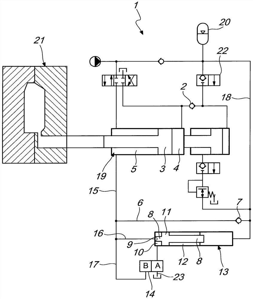
[0017] DETAILED DESCRIPTION OF THE PREFERRED EMBODIMENTS With reference to the cited figures, an injection assembly according to the invention, indicated generally by reference numeral 1 , comprises an injection cylinder 19 suitable for injecting liquid metal into a mold 21 .

[0018] According to the invention, the oil pressure control circuit has only one control valve 22 which is inserted at the input between the accumulator 20 and the injection cylinder 19 and which controls the entire profile of the injection process.

[0019] The hydraulic fluid required to move the injection cylinder 19 is drawn from the accumulator 20 and introduced into the piston-side chamber 4 of the injection cylinder 19 by means of the control valve 22 and the non-return valve 2 .

[0020] The accumulator 20 contains hydraulic fluid at a given pressure.

[0021] The injection cylinder 19 is also provided with an annular chamber 5 which is connected to the accumulator 20 by means of the conduit 15 ...


PUM


Abstract

An injection assembly for a die casting system having an injection cylinder adapted to inject liquid metal into a casting cavity; the injection cylinder is actuated by hydraulic flow from an oil pressure control circuit; the oil pressure control circuit includes a hydraulic buffer, the hydraulic buffer The device blocks and releases the flow of hydraulic fluid in the injection cylinder and provides a preset value of back pressure in order to control the injection speed in the injection cylinder and prevent cavitation.

Description

technical field [0001] The present invention relates to an injection assembly for a die casting system. Background technique [0002] As is known, die casting systems have an injection assembly which has the function of filling the casting cavity with liquid metal. [0003] Conventional injection assemblies have an injection cylinder actuated by an oil pressure control circuit. [0004] Today's injection systems suffer from severe cavitation problems and the result are pressure spikes and very high temperatures. [0005] These phenomena occur when the injection cylinder stops suddenly after filling the mold with metal as it moves. [0006] Due to the sudden stop of the injection piston, the hydraulic oil column pushed outwards at high speed from the annular chamber of the injection cylinder ruptures, causing cavitation, resulting in pressure peaks and high temperatures (diesel effect). [0007] The cavitation triggered during the injection step in the annular branch of th...

Claims


Application Information

Patent Timeline
Patent Type & Authority Patents(China)
IPC IPC(8): B22D17/20B22D17/32B29C45/82
CPCB22D17/203B22D17/2046B29C45/82B22D17/22B22D17/32B29C2945/76498
Inventor F·迪奥尼R·奥伯尔
Owner IDRA
Why Eureka
Try Eureka