Real-time detection method for multi-axis linkage contour error
A contour error and real-time detection technology, which is applied in the direction of instruments, computer control, simulators, etc., can solve the problems of long calculation time and poor estimation accuracy, and achieve the effect of avoiding excessive calculation time and good real-time performance
- Summary
- Abstract
- Description
- Claims
- Application Information
AI Technical Summary
Problems solved by technology
Method used
Image

Examples
Embodiment 1
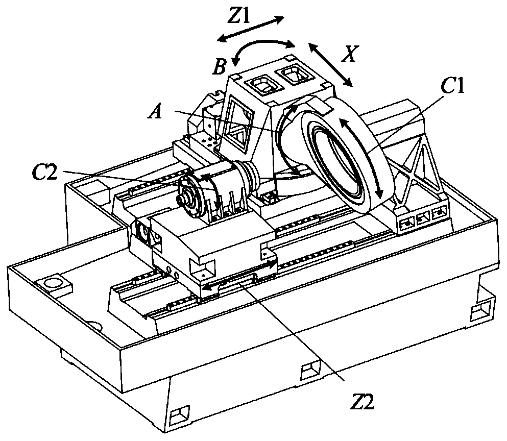
[0044] see figure 2 , the present embodiment carries out the test on the powerful gear honing machine tool for inner gear honing wheel. The B axis is the rotation axis, the angle unit is rad, the Z1 axis is the linear axis, and the length unit is mm. The number of teeth of the workpiece gear to be processed is 73, the modulus is 2.25mm, the helix angle is 31 degrees, the direction is right-handed, and the tooth width is 50mm. The parametric equation of the expected trajectory of each axis of the CNC machine tool is P(u)=[φ C1 ,φ Z1 ,φ C2 ,φ A ,φ B ], the parameter equations of each axis are as follows:
[0045]
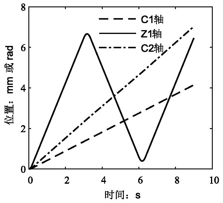
[0046] The value range of parameters corresponding to the trajectory is [0,6], and the unit is time s. The values of each parameter are shown in Table 1, and the corresponding trajectories of each axis are shown in image 3 and Figure 4 shown.
[0047] Table 1 Each parameter value in the parameter track
[0048]
[0049] (1) Read the actual points ...
Embodiment 2
[0059] see Figure 7 , the present embodiment is tested on a five-axis CNC machining platform. The CNC machine tool includes five motion axes of X-axis, Y-axis, Z-axis, A-axis, B-axis and C-axis, wherein X-axis, Y-axis and Z-axis are Linear feed axis, length unit is mm, A axis, C axis is rotary feed axis, angle unit is rad, B axis is tool spindle, angle unit is rad. The workpiece to be processed is the crown surface of solid zirconia material. This surface is a free-form surface, and a part of the movement path is taken. The parameter equation of the expected trajectory of each axis is P(u)=[φ X ,φ Y ,φ Z ,φ A ,φ C ], the parametric equation of each axis is φ X = φ X (u), φ Y = φ Y (u), φ Z = φ Z (u), φ A = φ A (u), φ C = φ C (u); the trajectory of each axis with respect to time is as follows Figure 8 and Figure 9 shown.
[0060] (1) Read the actual points of each axis in each position control cycle Calculate the actual point P a The distance to any point...
Embodiment 3
[0070] see Figure 12 , this embodiment is tested on a three-axis CNC machining platform. The CNC machine tool includes three linear feed axes of X axis, Y axis, and Z axis. The length unit is mm, the B axis is the tool spindle, and the angle unit is rad. The workpiece to be processed is a saddle-shaped surface, which is a hyperbolic paraboloid, and the surface equation is as follows:
[0071] φ Z = φ X 2 / 4-φ Y 2 / 9-5
[0072] The parameter equation of the desired trajectory of each axis is P(u)=[φ X ,φ Y ,φ Z ], the parametric equation φ of each axis X = φ X (u), φ Y = φ Y (u), φ Z = φ Z (u); the trajectory of each axis with respect to time is as follows Figure 13 shown.
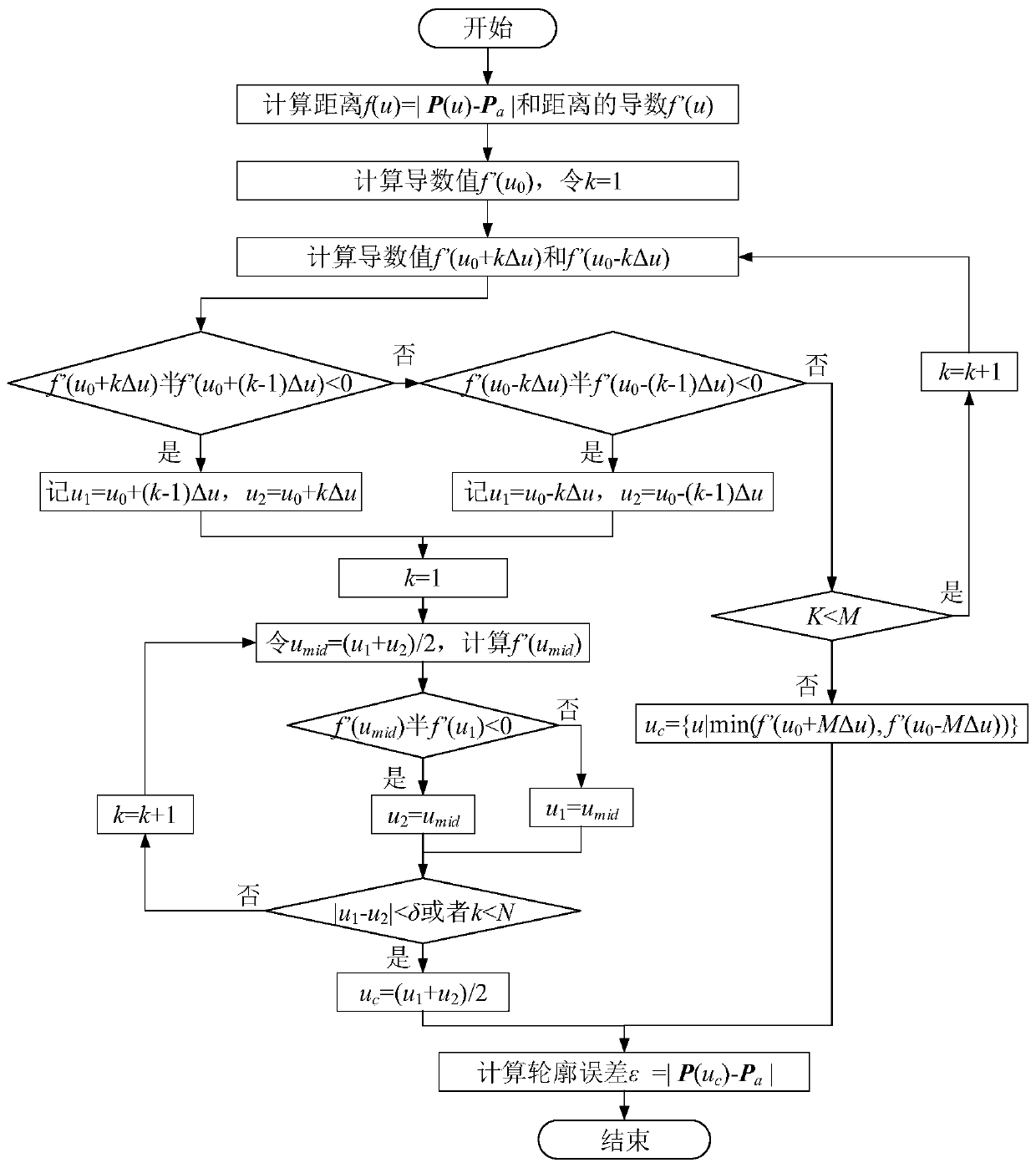
[0073] (1) Read the actual points of each axis in each position control cycle Calculate the actual point P a The distance to any point on the desired trajectory is:
[0074]
[0075] Calculate the derivative of the distance f(u) with respect to the parameter u as f'(u);
[0076] (2...
PUM
 Abstract
Description
Claims
Application Information
 - R&D
- Intellectual Property
- Life Sciences
- Materials
- Tech Scout
- Unparalleled Data Quality
- Higher Quality Content
- 60% Fewer Hallucinations
Browse by: Latest US Patents, China's latest patents, Technical Efficacy Thesaurus, Application Domain, Technology Topic, Popular Technical Reports.
© 2025 PatSnap. All rights reserved.Legal|Privacy policy|Modern Slavery Act Transparency Statement|Sitemap|About US| Contact US: help@patsnap.com