A Design Method for Expanding Diffraction Image

A design method and image technology, applied in optical components, instruments, optics, etc., can solve the problems of image aliasing and diffraction image size limitation, and achieve the effect of expanding the maximum size without image aliasing.

Active Publication Date: 2020-10-27
TSINGHUA UNIV
View PDF0 Cites 0 Cited by
  • Summary
  • Abstract
  • Description
  • Claims
  • Application Information

AI Technical Summary

Problems solved by technology

from figure 1 (c) It can be seen that if the size of the calculated diffraction image exceeds the period λz / Δx 0 , there will be image aliasing, which will limit the size of the diffraction image. Therefore, it is necessary to obtain a larger diffraction image without changing the DOE sampling interval

Method used


Image

  • A Design Method for Expanding Diffraction Image
  • A Design Method for Expanding Diffraction Image
  • A Design Method for Expanding Diffraction Image

Examples


Embodiment Construction

[0052] figure 2 What is shown is the optical path diagram of this scheme, 1 is parallel light, 2 is diffractive optical device (DOE), 3 is low-pass filter (the position where low-pass filter is set is the middle plane), and 4 is the output plane. Taking one-dimensional as an example, the specific scheme is as follows:

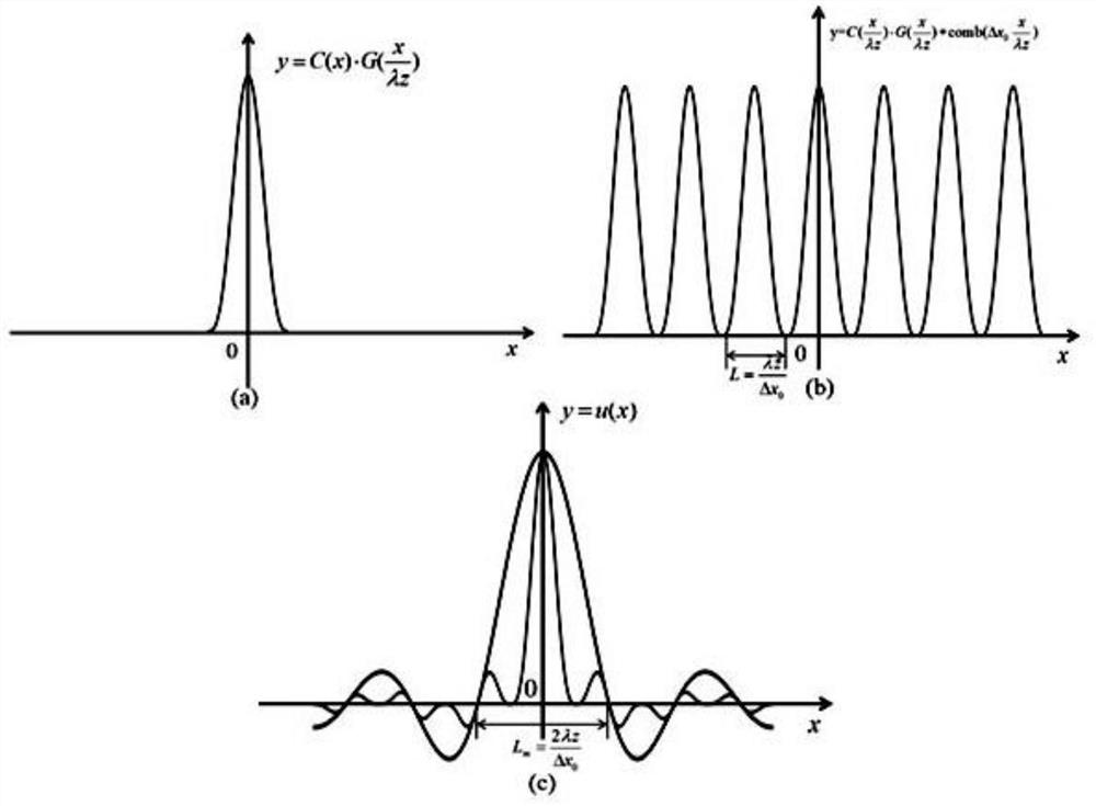
[0053] The first step is the Fresnel diffraction from the DOE to the intermediate plane, and the light field distribution on the intermediate plane can be expressed as

[0054]

[0055] where x 0 , x 1 Represent the coordinates of the input surface and the intermediate surface, respectively, u0 (x 0 ) is the light field distribution just after passing through the DOE, z 1 is the distance from the input plane to the middle plane, λ is the wavelength of the incident parallel light, k=2π / λ is the wave vector, stands for the Fourier transform. In most cases, it is difficult to obtain the analytical solution of formula (1), so numerical calculation is req...


PUM


Abstract

The invention discloses a design method for expanding a diffractive image, which belongs to the field of optical design. The method comprises steps: firstly, a virtual intermediate plane is set, and the optical field distribution on an output plane is calculated in two steps; zero-padding is carried out on an input plane wherein a diffractive optical element DOE is located; a low-pass filter is arranged on the intermediate plane for filtering, and image aliasing is eliminated; and in combination of an optimization algorithm, the DOE phase is optimized, the phase in a non-padding region is finally taken as the design phase of the DOE, and finally the purpose of expanding the diffractive image is achieved. The calculated maximum size of the diffractive image on the output plane can be effectively expanded, and no image aliasing occurs. The method can be used in laser manufacturing, dot matrix generation, holographic 2D / 3D display, gaming, entertainment and other fields.

Description

technical field [0001] The invention belongs to the field of optical design, in particular to a design method for enlarging a diffraction image. Background technique [0002] When a diffractive optical element (DOE) is illuminated with parallel light, the discretization of the DOE results in a limited size of the diffractive image on the output face. How to obtain larger diffraction images without reducing the sampling interval of diffractive optical elements and without image aliasing has always been a difficult problem in the field of optics. [0003] Suppose a diffractive optical element (DOE) is illuminated by a beam of parallel light, taking one-dimensional as an example, the light field distribution just after the beam passes through the DOE can be expressed by u(x 0 )express. Discretize the DOE phase, then the light field can be further expressed as [0004] [0005] Here comb stands for comb function; rect stands for rectangle function; x 0 is the coordinate o...

Claims


Application Information

Patent Timeline
Patent Type & Authority Patents(China)
IPC IPC(8): G02B27/00G02B27/42
CPCG02B27/0012G02B27/4205
Inventor 谭峭峰孔哲
Owner TSINGHUA UNIV
Why Eureka
Try Eureka