
Gantry crane unit based on combined type rail

A combined, gantry technology, applied in the field of gantry cranes, can solve the problems of different positions of different objects and rosin, and the inability to lift different objects at the same time.

Inactive Publication Date: 2019-08-23
钱月英
View PDF0 Cites 0 Cited by
  • Summary
  • Abstract
  • Description
  • Claims
  • Application Information

AI Technical Summary

Problems solved by technology

[0004] In order to solve the problem that different objects cannot be lifted at the same time and different objects and rosin cannot be placed in different positions, the present invention provides a gantry crane unit based on a combined track

Method used


Image

  • Gantry crane unit based on combined type rail
  • Gantry crane unit based on combined type rail
  • Gantry crane unit based on combined type rail

Examples


Embodiment 1

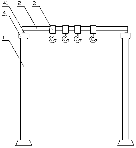
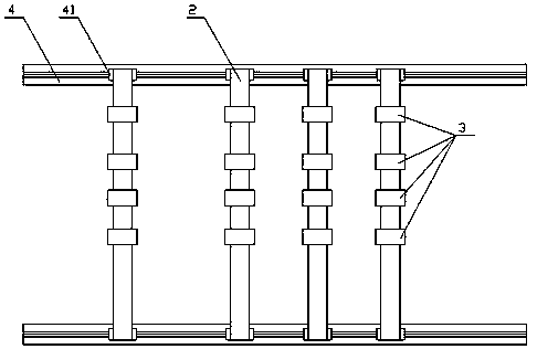
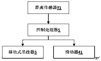
[0032] refer to Figure 1-3 , figure 1 A schematic diagram of a gantry crane unit based on a combined track provided by the present invention; figure 2 A top view schematic diagram of a track beam frame of a gantry crane unit based on a combined track provided by the present invention; image 3 A system block diagram of a gantry crane unit based on a combined track provided by the present invention.

[0033] Specifically, a gantry crane unit based on a combined track includes: a gantry support frame 1 , a gantry crane beam frame 2 , a mobile hanger 3 , and is characterized in that it also includes a track beam frame 4 and a control processor 5 .

[0034] The gantry support frame 1 includes a first support frame, a second support frame, a third support frame, and a fourth support frame, and the four are respectively arranged at four corners of a cubic space. The track beams 4 along the upper edge of the cubic space are respectively fixedly connected to the upper ends of two...

Embodiment 2

[0045] refer to Figure 4-5 , Figure 4 The second schematic diagram of the gantry crane beam frame of the gantry crane unit based on the combined track provided by the present invention; Figure 5 Appropriate figure for the track girder frame of the second combined track-based gantry crane set provided by the present invention.

[0046] This embodiment is basically the same as the first embodiment above, except that the mobile hangers of the same group have different heights. The width of the lower mobile hanger in the same group of mobile hangers is smaller than the width of another mobile hanger in the same group.

[0047] The mobile hangers 3 in the same group have different heights and widths, and the height and width of one mobile hanger 3 in the same group are higher and larger than the other mobile hanger 3 .

[0048] The higher one of the mobile hangers in the same group is provided with a through hole, and the through hole is used for another mobile hanger in the ...

Embodiment 3

[0053] refer to Figure 6-7 , Image 6 A top view schematic diagram of the track beam frame of the third combined track-based gantry crane unit provided by the present invention; Figure 7 A top view schematic diagram of the combined gantry crane unit of the third combined track-based gantry crane unit provided by the present invention.

[0054] This embodiment is basically the same as the first embodiment above, except that, preferably, the track beam frame 4 includes several sliding tracks 42 , and the sliders 41 are respectively located on different sliding tracks 42 . The same group of sliders 41 are mirror-symmetrical at the position of the sliding track 42 .

[0055] The track beam frame 4 is provided with a plurality of sliding tracks 42, and the sliding tracks 42 are parallel to each other. As one of the implementation manners, the distances between the sliding tracks 42 are consistent, several sliders 41 correspond to corresponding sliding tracks 42 , and one slidi...


PUM


Abstract

The invention relates to a gantry crane unit based on a combined type rail. The gantry crane unit comprises gantry supporting frames, gantry crane beam frames and movable type hanging devices. The gantry crane unit is characterized by further comprising rail beam frames and a control processor, wherein the gantry supporting frames comprise the first supporting frame, the second supporting frame, the third supporting frame and the fourth supporting frame, and the first supporting frame, the second supporting frame, the third supporting frame and the fourth supporting frame are arranged at fourcorners of a cubic space respectively; and the upper edge rail beam frames along the cubic space are fixedly connected with the upper ends of two adjacent gantry supporting frames respectively; a plurality of sliders are arranged on the rail beam frames, the two ends of the gantry crane beam frames are erected on the rail beam frames which are parallel to each other respectively, the two ends of the gantry crane beam frames are connected with the sliders on two sides of the gantry crane beam frames respectively, the plurality of movable type hanging devices are arranged, and the movable type hanging devices are arranged on the gantry crane beam frames and slide along the gantry crane beam frames; the movable type hanging devices are provided with a distance sensor which is connected with acontrol processor, and the distance sensor obtains the distance of the suspension point of a a suspended object, converts the distance of the suspension point into a suspension distance and outputs the suspension distance to the control processor.

Description

technical field [0001] The invention relates to the field of gantry cranes, in particular to a gantry crane unit based on a combined track. Background technique [0002] In some mold factory workshops, auto repair workshops, hardware factory workshops or outdoor docks, ports, etc., a large number of large parts, equipment or containers weighing more than 100KG need to be moved, debugged and installed every day. The weight that a single person can carry often requires five or six or more workers to work together to complete it, and no amount of workers can do it manually for large and overweight workpieces. With the acceleration of urbanization, all walks of life are gradually realizing semi-automatic mechanization and full-automatic mechanization to reduce labor intensity and improve production efficiency. Many enterprises have begun to introduce lifting devices to achieve mechanical lifting. At present, the commonly used mechanical lifting is Cranes using various driving p...

Claims


Application Information

Patent Timeline
Patent Type & Authority Applications(China)
IPC IPC(8): B66C5/02B66C11/04
CPCB66C5/02B66C11/04
Inventor 钱月英
Owner 钱月英
Learn More