
Robot control method, robot control device and robot

A control method and technology of a control device, applied in the field of robotics, can solve problems such as inappropriate lamina, uneven cutting quality, spinal nerve damage, etc., and achieve the effects of improving cutting quality, avoiding overcutting, and reducing spinal nerve damage.

Inactive Publication Date: 2019-08-23
SHENZHEN INST OF ADVANCED TECH CHINESE ACAD OF SCI
View PDF0 Cites 7 Cited by
  • Summary
  • Abstract
  • Description
  • Claims
  • Application Information

AI Technical Summary

Problems solved by technology

During this process, since the doctor needs to control the cutting allowance based on experience, there may be risks such as over-cutting causing spinal nerve damage, and the cutting quality is uneven in thickness
[0003] At present, the robots that can be applied to spinal surgery are mainly stereotaxic, such as Mazor X, Renaissance, ROSA, Tianji surgical robot, etc. These robots mainly play a guiding role in the process of pedicle screw placement. The direction of the screw path is a ray in the space, which can be determined directly by planning two points in the space in the standard two-dimensional and three-dimensional views; while the path of the decompression of the laminae is the irregular body data in the space, so the pedicle position The design of the nail is not suitable for decompression of the laminae

Method used


Image

  • Robot control method, robot control device and robot
  • Robot control method, robot control device and robot
  • Robot control method, robot control device and robot

Examples


Embodiment Construction

[0034] In the following description, specific details such as specific system structures and technologies are presented for the purpose of illustration rather than limitation, so as to thoroughly understand the embodiments of the present application. It will be apparent, however, to one skilled in the art that the present application may be practiced in other embodiments without these specific details. In other instances, detailed descriptions of well-known systems, devices, circuits, and methods are omitted so as not to obscure the description of the present application with unnecessary detail.

[0035] It should be understood that when used in this specification and the appended claims, the term "comprising" indicates the presence of described features, integers, steps, operations, elements and / or components, but does not exclude one or more other features. , whole, step, operation, element, component and / or the presence or addition of a collection thereof.

[0036] It shou...


PUM


Abstract

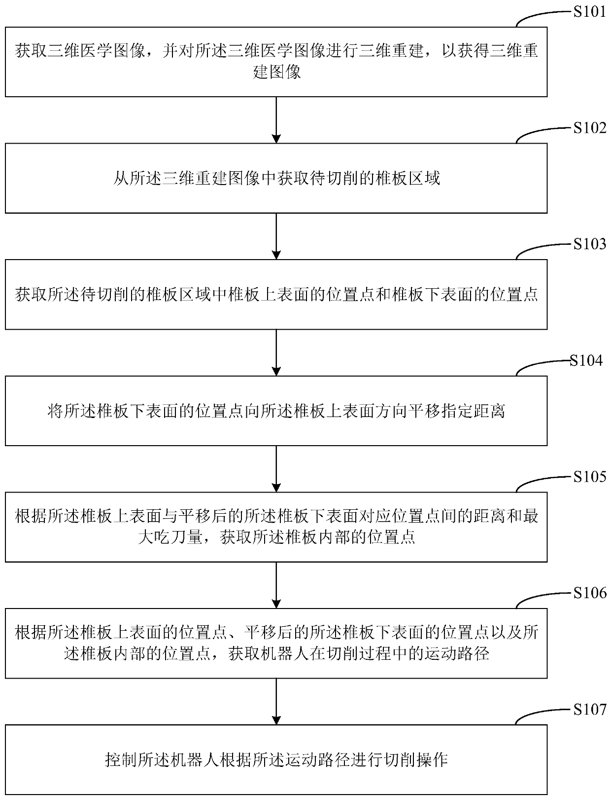
The invention is suitable for the technical field of robots and provides a robot control method, a robot control device, a robot and a computer readable storage medium. The robot control method comprises the steps that a three-dimensional medical image is obtained, and three-dimensional reconstruction is performed on the three-dimensional medical image to obtain a three-dimensional reconstructionimage; a vertebral plate area to be cut is obtained from the three-dimensional reconstruction image; position points of the upper surface of the vertebral plate and the position points of the lower surface of the vertebral plate are obtained; the position points of the lower surface of the vertebral plate are translated a specified distance towards the direction of the upper surface of the vertebral plate; the position points inside the vertebral plate are obtained according to the distances between the corresponding position points of the upper surface of the vertebral plate and the translated lower surface of the vertebral plate and the maximum engagement of the cutting edge; a moving path of the robot in the cutting process is obtained according to all the position points of the vertebral plate; and the robot is conteolled to perform cutting operations according to the moving path. By means of the robot control method, the robot control device, the robot and the computer readable storage medium, the robot can be conteolled to perform vertebral plate laminectomy, the cutting quality is improved, and spinal nerve injury caused by overcutting and other risks are reduced.

Description

technical field [0001] The present application belongs to the technical field of robots, and in particular relates to a robot control method, a robot control device, a robot and a computer-readable storage medium. Background technique [0002] Spinal stenosis is a common orthopedic disease. It causes compression of the dural sac, spinal cord or nerve roots due to the reduction in the size of the central canal, lateral groove or intervertebral foramen, which will cause a series of nerve-related diseases. Compression surgery is an important means of treatment of the disease. Laminar decompression includes complete decompression and limited decompression, mainly involving laminectomy, fenestration and other surgical methods. Taking unilateral fenestration as an example, doctors use tools such as ultrasonic osteotome or high-speed grinding drill to treat one side of the vertebral spinous process. The lamina is resected, and the lamina on the other side is cut until it is thin e...

Claims


Application Information

Patent Timeline
Patent Type & Authority Applications(China)
IPC IPC(8): B25J9/16B25J11/00
CPCB25J9/1602B25J9/1664B25J9/1679B25J11/00
Inventor 孙宇李猛苗燕茹徐艳雯胡颖
Owner SHENZHEN INST OF ADVANCED TECH CHINESE ACAD OF SCI
Learn More