
Plane two-freedom-degree parallel mechanism

A two-degree-of-freedom, two-plane technology, applied to manipulators, program-controlled manipulators, manufacturing tools, etc., can solve problems such as limited range of motion, many structural parts, and many hinge points, so as to ensure operational stability and modular scalability , to achieve the effect of flexible manufacturing

Pending Publication Date: 2019-08-23
无锡超通智能制造技术研究院有限公司
View PDF0 Cites 2 Cited by
  • Summary
  • Abstract
  • Description
  • Claims
  • Application Information

AI Technical Summary

Problems solved by technology

For most simple loading and unloading situations, two degrees of freedom can meet the requirements, and more degrees of freedom mean that functional redundancy is useless, operation and maintenance are difficult, and cost increases. Therefore, mechanisms with fewer degrees of freedom are used as much as possible to meet the action The need has long been a design goal in the industry
[0004] The current two-degree-of-freedom parallel mechanism is mainly realized by hinged connecting rods, most of which have the disadvantages of many structural parts, many hinge points, small movement space, and limited range of motion.

Method used


Image

  • Plane two-freedom-degree parallel mechanism
  • Plane two-freedom-degree parallel mechanism
  • Plane two-freedom-degree parallel mechanism

Examples


Embodiment 1

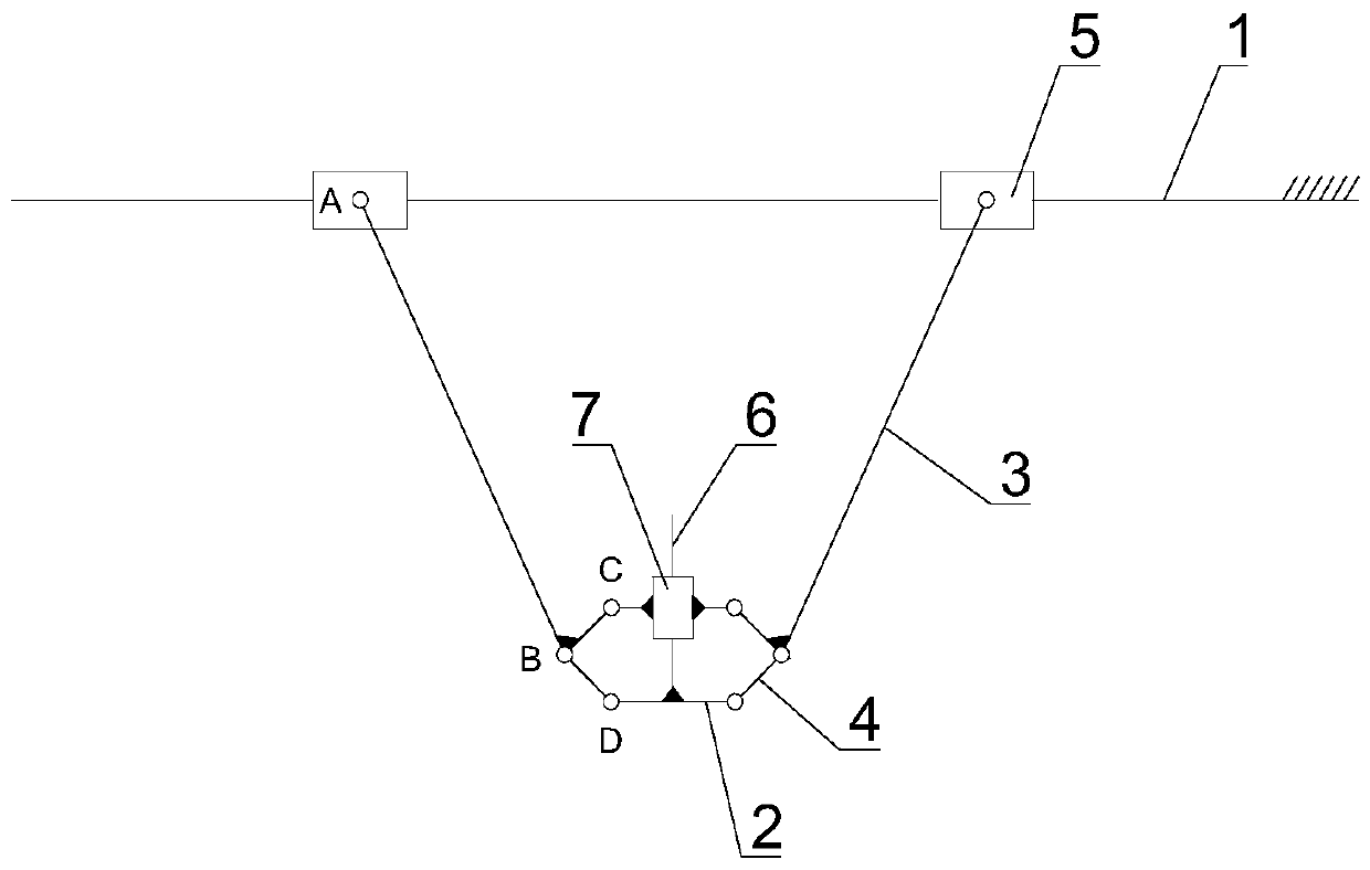
[0027] see figure 1 As shown, this embodiment provides a planar two-degree-of-freedom parallel mechanism, which includes a fixed guide rail 1 , a tool flange 2 , two members 3 and two connecting rods 4 .

[0028] The fixed guide rail 1 is provided with two driving sliding blocks 5 which respectively constitute moving pairs. The fixed guide rail 1 is fixed and the two driving sliding blocks 5 are independently driven by motors to move linearly along the fixed guide rail 1 . The moving pair can be slider guide rail, V-type guide rail roller, roller guide rail, linear bearing or dovetail groove guide rail slide table, and the driving mode can be belt drive, sprocket drive, rack and pinion drive or lead screw drive.

[0029] The tool flange 2 is used to install the external part, and two hinge points D are symmetrically arranged on both sides, and a balance slider 7 is arranged on it. The balance slider 7 moves along the axis perpendicular to the installation plane of the external...

Embodiment 2

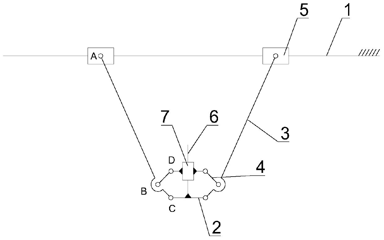
[0040] see figure 2 As shown, this embodiment is the deformation structure of Embodiment 1, the difference is that the balance slider 7 is symmetrically provided with two hinge points D, the hinge point D on the balance slider 7 is hinged with the other end of the connecting rod 4, and the balance The slider 7 is driven by the connecting rod 4 to move along the axis perpendicular to the installation plane of the outer part of the tool flange 2; Under the limit of 7, the installation plane of the external parts of the tool flange 2 always keeps moving in parallel with the fixed guide rail 1.

[0041]As shown in this embodiment, a plane XZ coordinate system is constructed with the second hinge point B as the origin, then the first hinge point A is located in the second quadrant of the XZ coordinate system, and the third hinge point C is located in the XZ coordinate system. In the fourth quadrant, the hinge point D is located in the first quadrant of the XZ coordinate system; t...

Embodiment 3

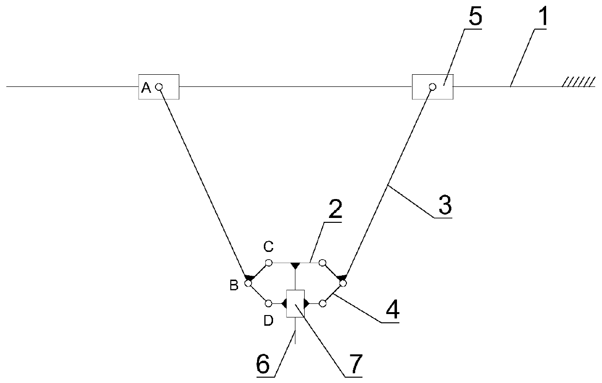
[0043] see image 3 As shown, this embodiment is the deformation structure of Embodiment 1, the difference is that the relative positions of the tool flange 2 and the balance slider 7 are opposite, then the third hinge point C of the member 3 is hinged with the tool flange 2, and the connecting rod 4 The other end is hinged with the balance slider 7. The rest of the structure is the same as that of Example 1.


PUM


Abstract

The invention discloses a plane two-freedom-degree parallel mechanism. The plane two-freedom-degree parallel mechanism comprises a fixed guiding rail, a tool flange, two members, and two connecting rods, wherein two driving sliding blocks forming moving pairs with the fixed guiding rail are arranged on the fixed guiding rail; the tool flange is used for mounting an outer connecting piece, a balancing sliding block is arranged on the tool flange, and the moving axis of the balancing sliding block is perpendicular to the straight line wherein the fixed guiding rail is located at; the two membersare distributed with the moving axis of the balancing sliding block as the central symmetry, a first hinging point, a second hinging point and a third hinging point sequentially distributed are arranged on each member, each hinging point is hinged to the corresponding driving sliding block to form a rotating pair, and each third hinging point is hinged to one of the tool flange or the balancing sliding block to form a rotating pair; and the two connecting rods are arranged corresponding to the members on the two sides, one end of each connecting rod is hinged to the second hinging point of the corresponding member to form a rotating pair, and the other end of each connecting rod is hinged to the balancing sliding block or the tool flange by being opposite to the corresponding third hinging point to form a rotating pair. By means of the plane two-freedom-degree parallel mechanism, the mounting plane of the outer connecting piece of the tool flange keeps always parallel to the axis of the fixed guiding rail.

Description

technical field [0001] The invention relates to the field of robot automation, in particular to a plane two-degree-of-freedom parallel mechanism. Background technique [0002] The plane two-degree-of-freedom parallel robot can realize any trajectory in the plane, and can be applied to high-speed tasks in the plane such as packaging, sorting, packaging, etc., so it has been widely used in automated production lines in light industry, electronics, food, and medicine industries. . [0003] Among them, handling, sorting, loading and unloading, etc. are the main application forms of robots. According to the needs of actions, robots have different degrees of freedom, including simple two degrees of freedom and complex multiple degrees of freedom. For most simple loading and unloading situations, two degrees of freedom can already meet the requirements. More degrees of freedom means redundant functions, difficult operation and maintenance, and increased costs. Therefore, a mechani...

Claims


Application Information

Patent Timeline
Patent Type & Authority Applications(China)
IPC IPC(8): B25J9/00
CPCB25J9/003
Inventor 赵飞李解梅雪松运侠伦刘斌孙孝飞
Owner 无锡超通智能制造技术研究院有限公司
Learn More