Supercharge Your Innovation With Domain-Expert AI Agents!

Electroplating process equipment

An electroplating process and equipment technology, which is applied in the field of electroplating process equipment, can solve the problems of reducing equipment production efficiency, reducing production efficiency, and inconvenient equipment work, and achieves the effects of facilitating the replacement of plated metals, improving work reliability, and reducing labor burden

Active Publication Date: 2019-08-20
杭州路客康复辅具技术有限公司
View PDF2 Cites 2 Cited by
  • Summary
  • Abstract
  • Description
  • Claims
  • Application Information

AI Technical Summary

Problems solved by technology

Electroplating refers to a surface processing method in which the cations of the pre-plated metal in the plating solution are deposited on the surface of the base metal by electrolysis with the base metal to be plated as the cathode in a salt solution containing pre-plated metal to form a coating. , in the traditional electroplating process, there are some problems, such as: it is difficult to put the plated metal into the reaction equipment, and there are many problems in the follow-up supplementary process, which makes the replacement of the plated metal very inconvenient and very large The production efficiency of the equipment is reduced to a certain extent, and in the general traditional equipment, when the workpiece is put into the equipment, more manual control is used to put the workpiece into the equipment by manual winding. While reducing the production efficiency, the equipment has to be shut down, and for different electroplating processes, it is necessary to repeatedly put the workpiece into different reaction vessels for efficient reaction, which greatly increases the equipment cost. Takes up space and makes equipment work extremely inconvenient

Method used


Image

  • Electroplating process equipment
  • Electroplating process equipment
  • Electroplating process equipment

Examples


Embodiment Construction

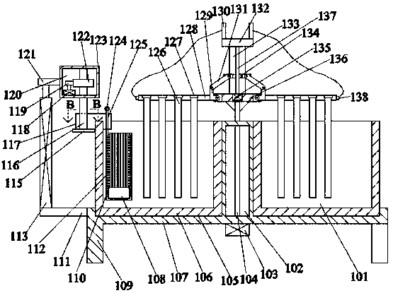
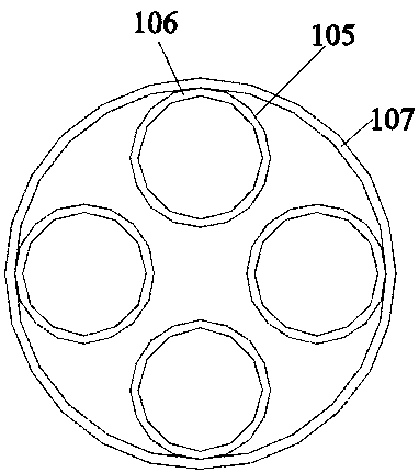
[0021] Such as Figure 1-Figure 3 As shown, the present invention is described in detail. For the convenience of description, the orientations mentioned below are now stipulated as follows: figure 1 The up, down, left, right, front and back directions of the projection relationship itself are consistent. A kind of electroplating process equipment of the present invention includes a base 107, and the base 107 is provided with a plurality of annular arrays and openings. A plurality of footings 109 against the ground, an inner chamber 102 positioned in the base 107 is arranged between the clamping chambers 105, a transmission motor 103 is fixed on the lower end of the base 107, and the power in the transmission motor 103 A power shaft 104 is connected, and the power shaft 104 rotates through the inner cavity 102 and extends upward. The upper end of the power shaft 104 is provided with a clamping device for clamping the workpiece for processing. A storage device for containing th...


PUM


Abstract

The invention discloses electroplating process equipment. The electroplating process equipment comprises a base, wherein a plurality of blocking cavities which are arranged in the form of an annular array and are provided with openings are arranged in the base; the lower end surface of the base is fixedly equipped with a plurality of ground pins which abut against ground; an inner cavity positioned in the base is arranged among the blocking cavities; the lower end surface of the base is fixedly equipped with a transmission motor; a power shaft is in power connection in the transmission motor;and the power shaft rotataly penetrates through the inner cavity and extends upwards. The electroplating process equipment is simple in structure, adopts a clamping device, an accommodating device anda lifting device, realizes a way of swinging and rotating workpieces conveniently, and freely converting the workpieces among different reaction containers, and has a function of conveniently replacing plating metal, so that working reliability of the equipment is greatly improved, operation of staff is more convenient, and labor burden of the staff is reduced.

Description

technical field [0001] The invention relates to the technical field of electroplating process equipment, in particular to electroplating process equipment. Background technique [0002] The electroplating process uses the principle of electrolysis to coat a conductor with a layer of metal. Electroplating refers to a surface processing method in which the cations of the pre-plated metal in the plating solution are deposited on the surface of the base metal by electrolysis with the base metal to be plated as the cathode in a salt solution containing pre-plated metal to form a coating. , in the traditional electroplating process, there are some problems, such as: it is difficult to put the plated metal into the reaction equipment, and there are many problems in the follow-up supplementary process, which makes the replacement of the plated metal very inconvenient and very large The production efficiency of the equipment is reduced to a certain extent, and in the general traditi...

Claims


Application Information

Patent Timeline
IPC IPC(8): C25D19/00C25D17/00
CPCC25D17/00
Inventor 不公告发明人
Owner 杭州路客康复辅具技术有限公司
Features
  • R&D
  • Intellectual Property
  • Life Sciences
  • Materials
  • Tech Scout
  • Unparalleled Data Quality
  • Higher Quality Content
  • 60% Fewer Hallucinations
Learn More