
Wastewater treatment system

A wastewater treatment system and wastewater technology, applied in water/sewage treatment, neutralized water/sewage treatment, water/sewage treatment equipment, etc., can solve high operating costs, low rising flow rate, reverse osmosis system fouling and scaling and other issues, to achieve the effect of realizing resource utilization, reducing operating costs, and stabilizing effluent quality

Pending Publication Date: 2019-08-20
FOCUSED PHOTONICS
View PDF0 Cites 1 Cited by
  • Summary
  • Abstract
  • Description
  • Claims
  • Application Information

AI Technical Summary

Problems solved by technology

[0005] 1. Due to the high concentration of Ca in the wastewater 2+ , Mg 2+ Ions, the precipitate formed after dosing is more, and it exists in the form of colloid, the density is low, and it is not easy to precipitate. The clarifier needs to be set at a very low rising flow rate to meet the clarification effect requirements, resulting in a very large cross-sectional area of ​​the clarifier. , covering a huge area
[0006] 2. The clarification tank is greatly affected by the environment (mainly affected by temperature changes) and fluctuations in the quality and quantity of incoming water. Although the clarification tank has a sufficiently large cross-sectional area and the wastewater has a sufficiently low rising flow rate, there will still be some Mg(OH ) 2 , CaSO 4 , CaCO 3 As the wastewater flows into the reverse osmosis system, the effluent effect is unstable. Once a large amount of solid precipitated matter flows into the subsequent reverse osmosis treatment system with the wastewater, it will cause fouling and scaling of the reverse osmosis system, and it is not easy to recover
[0007] 3. Due to the wastewater Ca 2+ , Mg 2+ The ion concentration is very high, and a large amount of Ca(OH) needs to be added 2 and Na 2 CO 3 , resulting in very high operating costs
[0008] 4. Since the wastewater is high-concentration wastewater, the ion content in the wastewater is very high, and a large amount of solid precipitated substances will be produced after dosing, resulting in a large amount of sludge (solid waste) that needs to be disposed of in the wastewater treatment system every year, and resource utilization cannot be realized

Method used


Image

  • Wastewater treatment system

Examples


Embodiment Construction

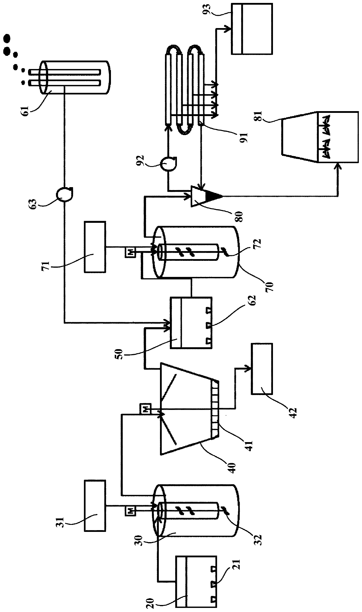
[0045] figure 1 is a schematic structural diagram of a wastewater treatment system according to an embodiment of the present invention. Such as figure 1 As shown, the embodiment of the present invention provides a wastewater treatment system. The wastewater treatment system includes a primary flocculation reaction tank 30, Ca(OH) 2 Dosing system 31, primary clarification tank 40, secondary flue gas reaction tank 50 and flue gas adding device. The primary flocculation reaction tank 30 is configured to receive wastewater. Ca(OH) 2 The dosing system 31 is configured to add Ca(OH) to the primary flocculation reaction tank 30 2. The primary clarification tank 40 communicates with the primary flocculation reaction tank 30 to receive the wastewater in the primary flocculation reaction tank 30 . The secondary flue gas reaction tank 50 communicates with the primary clarifier 40 to receive the waste water in the primary clarifier 40 . The flue gas adding device is configured to ...


PUM


Abstract

The invention provides a wastewater treatment system. The wastewater treatment system comprises a primary flocculation reaction tank, which is used to receive wastewater; a Ca(OH)2 adding system, which is used to add Ca(OH)2 into the primary flocculation reaction tank; a primary clarification tank, which is communicated with the primary flocculation reaction tank and is used to receive wastewaterin the primary flocculation reaction tank; a secondary flue gas reaction tank, which is communicated with the primary clarification tank and is used to receive wastewater in the primary clarificationtank; and a flue gas addition device, which is used to introduce flue gas into the secondary flue gas reaction tank so that flue gas can react with wastewater in the secondary flue gas reaction tank.Due to the secondary flue gas reaction tank, waste factory flue gas is introduced into the system, the addition amount of Na2CO3 is largely reduced, the operation cost is reduced; and when the Ca<2+>concentration of the wastewater is greater than Mg<2+> concentration of the wastewater, the aeration amount of flue gas is controlled so that Na2CO3 is not needed any more.

Description

technical field [0001] The invention relates to the field of wastewater treatment, in particular to a wastewater treatment system. Background technique [0002] High SS (suspended solids ≥ 1000mg / L), high hardness (refers to Ca in solution 2+ , Mg 2+ Isohard ion content ≥ 1000mg / L), high-salt wastewater must reduce the content of chloride ions in the wastewater if it wants to meet the requirements of discharge after treatment, and reverse osmosis technology is usually used to concentrate the wastewater, and the produced water can be reused or directly discharged , after the concentrated solution is further concentrated, industrial salt is produced through evaporation and crystallization; due to the high concentration of suspended solids, Ca 2+ , Mg 2+ Such as hardness ions, directly entering the reverse osmosis system will cause serious fouling and scaling of the reverse osmosis membrane, resulting in the failure of the reverse osmosis system to work normally. Therefore, ...

Claims


Application Information

Patent Timeline
IPC IPC(8): C02F9/04
CPCC02F9/00C02F1/5245C02F1/66C02F1/444C02F2101/10C02F2201/007
Inventor 陈侠胜尚菊红张毅王培城薛凯元李平
Owner FOCUSED PHOTONICS
Learn More