
Clamping device used for automatic welding of bumper

An automatic welding and clamping device technology, applied in auxiliary devices, welding equipment, auxiliary welding equipment, etc., can solve problems such as difficult to achieve quality stability and controllability, unfavorable cost control of enterprises, and low labor efficiency of workers , to achieve the effect of improving labor production efficiency, beautiful appearance, and improving the efficiency of loading and unloading parts

Inactive Publication Date: 2019-08-20
NANJING ENIGMA IND AUTOMATION TECH CO LTD
View PDF0 Cites 6 Cited by
  • Summary
  • Abstract
  • Description
  • Claims
  • Application Information

AI Technical Summary

Problems solved by technology

Traditional bumper welding is difficult to achieve quality stability and controllability due to the influence of manual welding speed, wire feeding speed, welding posture, etc.; in addition, the labor efficiency of workers is low, the labor intensity is high, and the operation requirements for workers are high. Conducive to enterprise cost control, etc. are also the drawbacks of existing technologies

Method used


Image

  • Clamping device used for automatic welding of bumper
  • Clamping device used for automatic welding of bumper
  • Clamping device used for automatic welding of bumper

Examples


Embodiment Construction

[0032] The present invention will be further illustrated below in conjunction with the accompanying drawings and specific embodiments. This embodiment is implemented on the premise of the technical solution of the present invention. It should be understood that these embodiments are only used to illustrate the present invention and are not intended to limit the scope of the present invention.

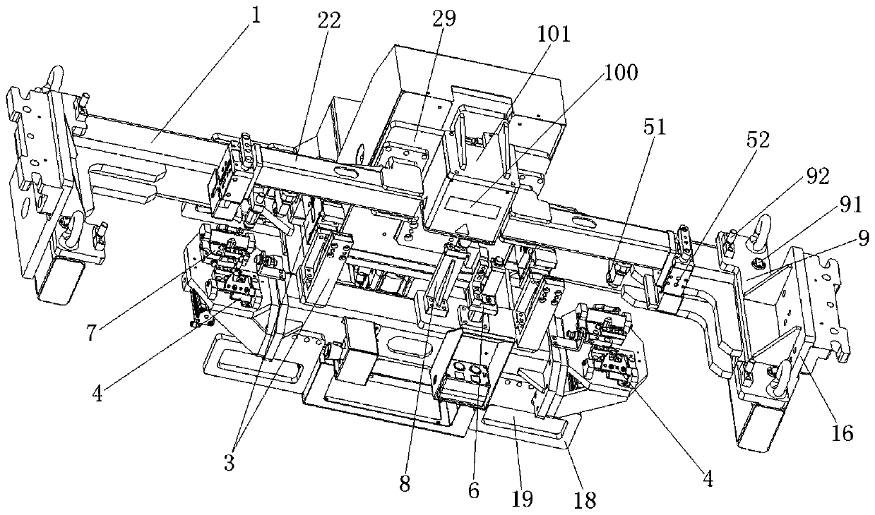
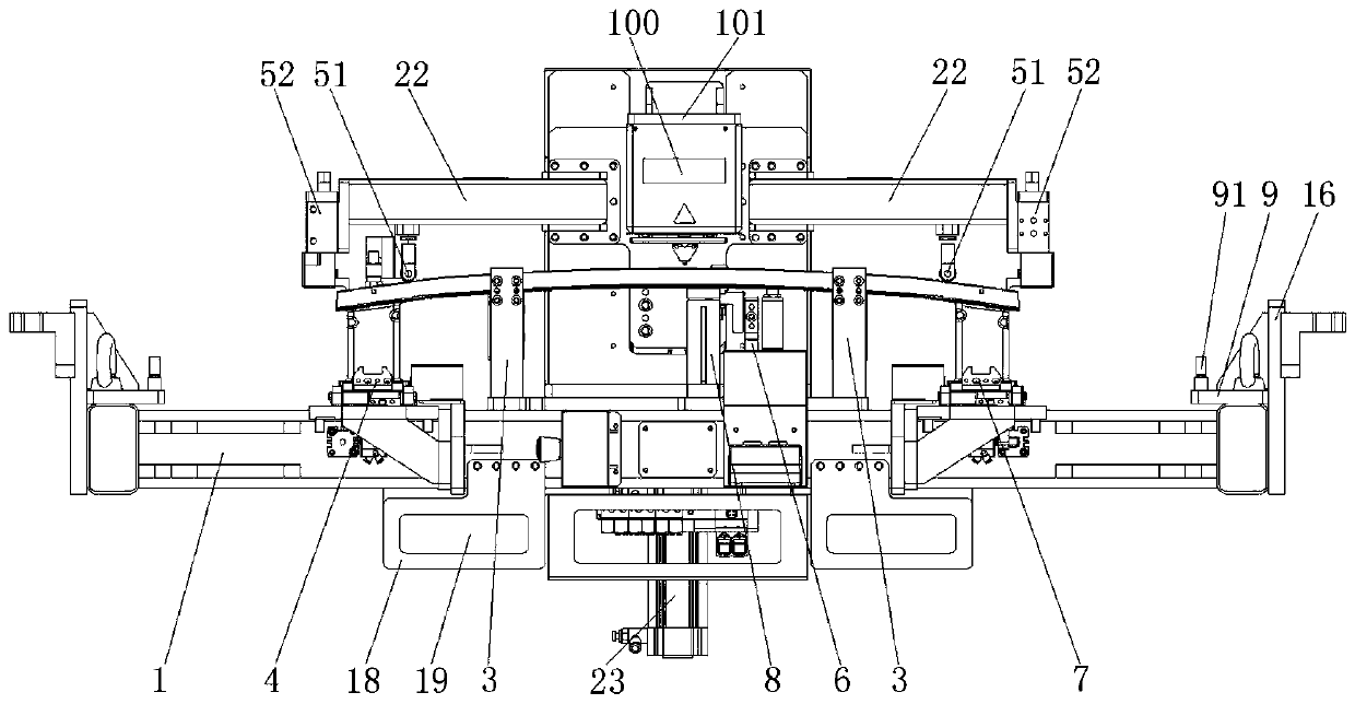
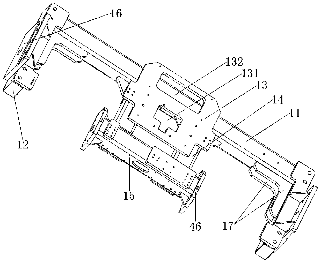
[0033] Such as Figures 1 to 12 As shown, the embodiment of the present invention provides a clamping device for automatic bumper welding, the device includes an underframe 1, and the upper side of the underframe 1 is provided with a crash box clamping mechanism 4 and a main beam pressing mechanism. Wherein, the crash box clamping mechanism 4 includes two groups, which are respectively used to fix a crash box. Two groups of energy-absorbing box clamping mechanisms 4 are respectively arranged on the upper sides of the chassis 1 , and the main beam pressing mechanism includes a downward p...


PUM


Abstract

The invention discloses a clamping device used for automatic welding of a bumper. The clamping device comprises a base frame. Two energy-absorption box clamping mechanisms and a girder pressing mechanism are arranged on the upper side of the base frame. The two energy-absorption box clamping mechanisms are separately located on the two sides of the base frame. The girder pressing mechanism comprises a downward pressing mechanism and a lateral pressing mechanism. The downward pressing mechanism comprises a supporting frame arranged on the upper side of the base frame and a jacking assembly arranged behind the supporting frame. The jacking assembly is connected with pressing beams and is used for adjusting up-down movement of the pressing beams. The pressing beams are oppositely arranged onthe two sides of the jacking assembly. Girder pressing assemblies used for pressing a girder on the upper sides of energy-absorption boxes are arranged on the pressing beams. The lateral pressing mechanism comprises a plurality of lateral pressing cylinders fixed to the upper side of the base frame. The lateral pressing cylinders are connected with lateral pressing blocks. Girder limiting blocks are oppositely arranged on the lateral pressing blocks. The lateral pressing cylinders are used for pressing the girder between the lateral pressing blocks and the girder limiting blocks. By adoption of the clamping device used for automatic welding of the bumper, automatic welding can be achieved, a weld joint can be formed at a time, the welding reliability is improved, and the labor productivityis improved.

Description

technical field [0001] The invention relates to the field of automatic welding of bumpers, in particular to a clamping device for automatic welding of bumpers. Background technique [0002] With the development of the automobile industry, the automobile bumper, as an important safety device, is also on the road of innovation. In addition to maintaining the original protection function, the front and rear bumpers of today's automobiles also pursue harmony and unity with the body shape, and pursue their own lightweight. Since the bumper of a car can absorb and relieve external impact and protect the body and passengers, the quality of the bumper is very important at this time, and the welding quality is the most critical. Traditional bumper welding is difficult to achieve quality stability and controllability due to the influence of manual welding speed, wire feeding speed, welding posture, etc.; in addition, the labor efficiency of workers is low, the labor intensity is high...

Claims


Application Information

Patent Timeline
IPC IPC(8): B23K37/04B23K37/02B23K37/00
CPCB23K37/0435B23K37/0247B23K37/00B23K2101/006Y02P70/10
Inventor 徐楠华李长伟王小满程远
Owner NANJING ENIGMA IND AUTOMATION TECH CO LTD
Learn More