Digital irrigation and ablation equipment
A transmission device and a rotating device technology, applied in the field of medical equipment, can solve problems such as inability to realize flushing and suction, unfavorable flushing and suction, slow recovery of incision, etc., and achieve the effect of wide adjustment range, strong surgical adaptability, and smooth movement
- Summary
- Abstract
- Description
- Claims
- Application Information
AI Technical Summary
Problems solved by technology
Method used
Image
Examples
Embodiment 1
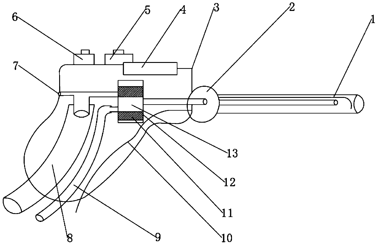
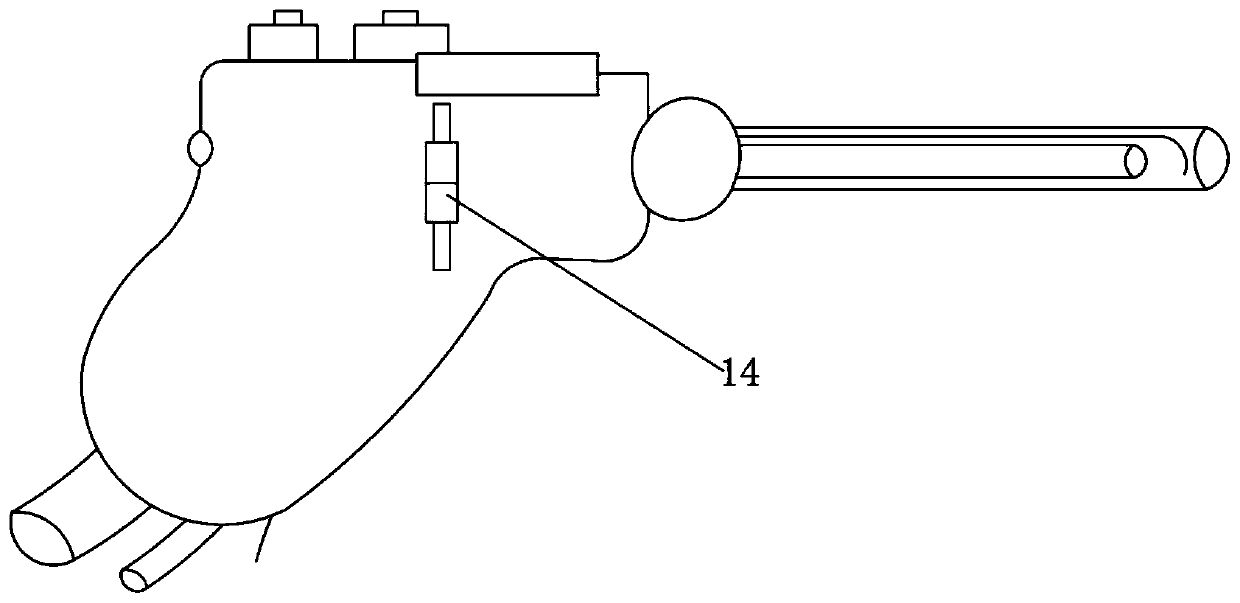
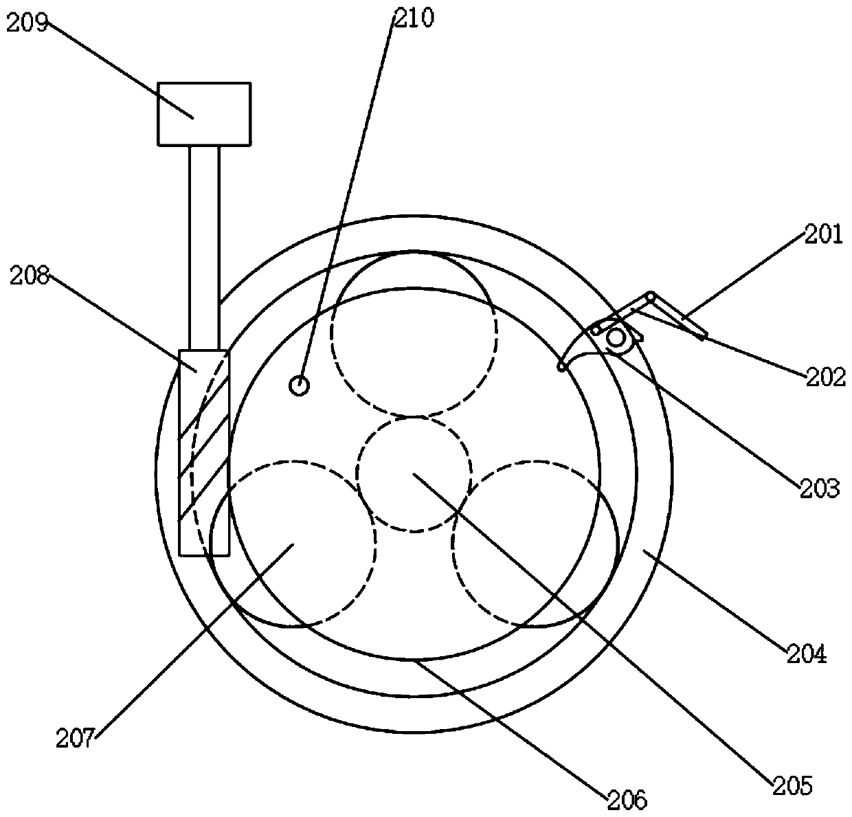
[0074] The digital flushing and ablation device mentioned above, such as figure 1 , figure 2 , image 3 , Figure 8 and Figure 10 As shown, it includes a control unit, a power unit, a flushing unit 9 and a suction unit 8. The power unit is connected to the flushing unit 9 to provide power for the flow of the flushing liquid in the flushing unit 9. The control unit is electrically connected to the power unit to control the power of the power unit. action; it also includes a housing 3, an ablation device 1, a conversion unit, an angle adjustment device 2 and a suction joint 31, wherein,
[0075] The ablation device 1 is installed inside the irrigation joint 31, and the ablation device 1 is used to ablate the cells of the surgical incision to accelerate the healing of the incision; the irrigation and suction joint 31 is connected to the angle adjustment device 2, and the irrigation and suction joint 31 is used to treat the surgical incision. At the same time, use the flushi...
Embodiment 2
[0106] This embodiment relates to a digital ablation device. Compared with Embodiment 1, the structure of the conversion unit is different, and the other structures are the same. Here, the structure of the conversion unit will be described in detail, and other structures will not be described in detail, as Figure 4 and 5 shown.
[0107] The conversion unit includes a conversion chamber body 26, a conversion chamber 25 and a transfer switch. The conversion chamber 25 is fixedly connected to the transfer switch. The conversion chamber 25 is provided with the inside of the conversion chamber body 26. The conversion chamber 25 is a tubular structure. Inside the body 3, and the conversion chamber 25 are provided with a flushing hole 22 and a suction hole 19, the distance between the flushing hole 22 and the suction hole 19 is not greater than the sliding stroke of the conversion chamber 25, that is, between the flushing hole 22 and the suction hole 19 The distance is less than or...
Embodiment 3
[0124] Compared with Embodiment 2, this embodiment has a different structure of the transfer switch, and other structures are the same. Here, only the specific structure of the transfer switch will be described, and other identical structures will not be described in detail, such as Figure 6 and 7 shown.
[0125] The transfer switch includes a conversion part 30, a transmission part 28, a moving part 29 and a guide part 27. The transmission part 28, the moving part 29 and the guide part 27 are all arranged inside the conversion chamber body 26, the conversion part 30 is connected with the transmission part 28, and the moving part 29 is fixedly connected with the conversion cavity 25, and the guide 27 is arranged on the inner wall of the conversion cavity body 26, and the moving part 29 is slidably fitted with the guide 27, so that the moving part 29 can slide relative to the guide 27; the transmission part 28 and The moving part 29 is rotationally matched, so that the rotati...
PUM
 Abstract
Description
Claims
Application Information
 - R&D
- Intellectual Property
- Life Sciences
- Materials
- Tech Scout
- Unparalleled Data Quality
- Higher Quality Content
- 60% Fewer Hallucinations
Browse by: Latest US Patents, China's latest patents, Technical Efficacy Thesaurus, Application Domain, Technology Topic, Popular Technical Reports.
© 2025 PatSnap. All rights reserved.Legal|Privacy policy|Modern Slavery Act Transparency Statement|Sitemap|About US| Contact US: help@patsnap.com


