A passive deployable antenna mechanism
A passive extension and antenna technology, applied to antennas, folded antennas, antennas suitable for movable objects, etc., can solve the problems of undiscovered and uncollected data, and achieve simple structure, light weight, and large rotation range Effect
Active Publication Date: 2014-06-25
SHANGHAI AEROSPACE SYST ENG INST
View PDF0 Cites 10 Cited by
- Summary
- Abstract
- Description
- Claims
- Application Information
AI Technical Summary
Problems solved by technology
At present, there is no description or report of the similar technology of the present invention, and no similar data at home and abroad have been collected yet.
Method used
View moreImage
Smart ImageViewing Examples
Examples
Embodiment Construction
Login to View More PUM
 Abstract
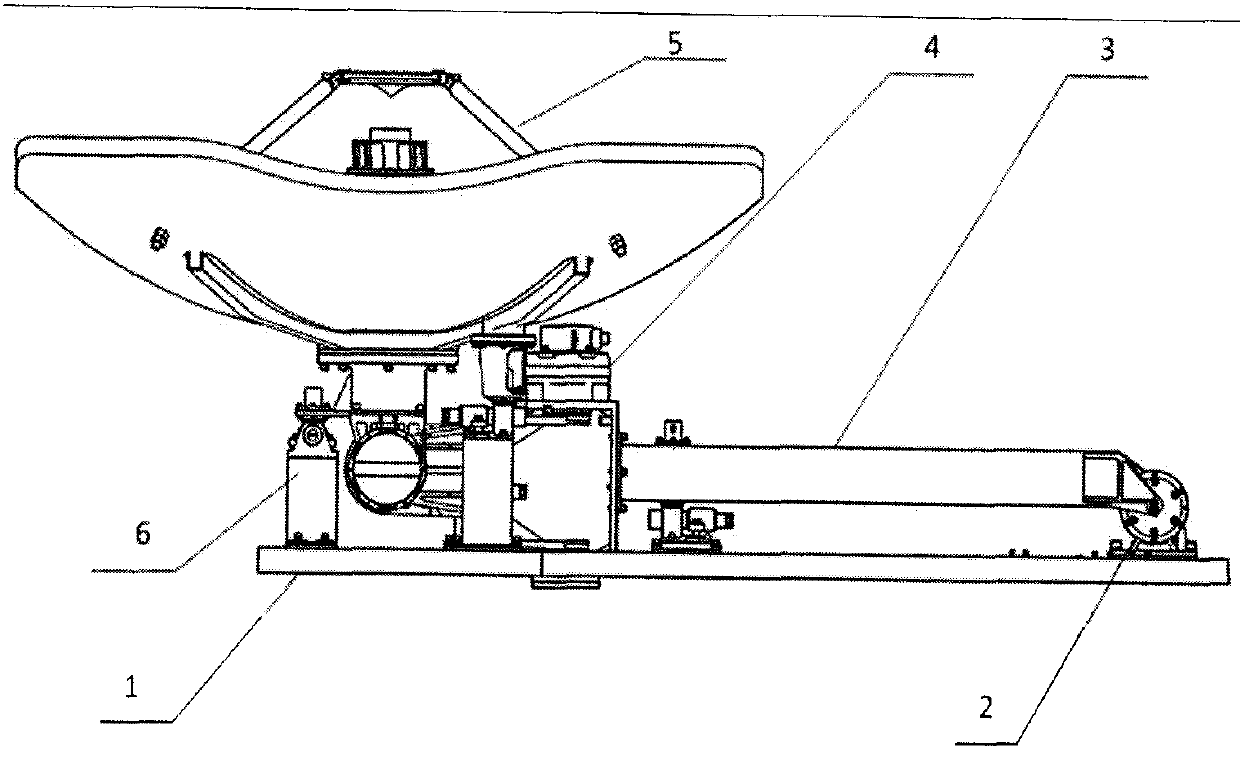
A passive deployable antenna mechanism is provided, which is characterized in that the device comprises: an antenna mounting plate (1), a damping speed stabilization mechanism (2), an antenna unfolding arm (3), a two-dimensional pointing mechanism (4), a spaceborne Antenna (5) and compression release device (6), damping and speed-stabilizing mechanism (2) are fixedly installed on one end of antenna mounting plate (1), and one end of antenna expansion arm (3) is connected with damping and speed-stabilizing mechanism (2), and another One end is connected to one end of the two-dimensional pointing mechanism (4), and the other end of the two-dimensional pointing mechanism (4) is connected to the satellite antenna (5), and the compression release device (6) is installed on the antenna unfolding arm (3), two Between the three-dimensional pointing mechanism (4), the spaceborne antenna (5) and the antenna mounting plate (1), it is used for locking the antenna mechanism in the satellite launching state, and releasing the antenna mechanism after the satellite enters orbit.
Description
technical field The invention relates to an antenna mechanism, in particular to a passive deployable antenna mechanism. technical background The antenna mechanism is an important executive device of the space-borne antenna. Its main function is to lock the space-borne antenna in the satellite launch state, meet the structural size requirements of the storage state and the vibration requirements of the active section of the launch, and realize the space-borne antenna after the satellite enters orbit. The outside of the cabin is lifted away from the satellite body, and the two-dimensional pointing mechanism is driven to swing left and right at a limited angle according to the requirements of the control system, driving the space-borne antenna to move in space. Some existing antenna mechanisms do not have the function of deployment, and contain a one-dimensional pointing mechanism, which drives the satellite-borne antenna to rotate at a small angle, and the spatial range of mo...
Claims
Login to View More Application Information
Patent Timeline
 IPC IPC(8): H01Q1/28H01Q3/08H01Q1/08
Inventor 崔琦峰杨金平
Owner SHANGHAI AEROSPACE SYST ENG INST
Features
- R&D
- Intellectual Property
- Life Sciences
- Materials
- Tech Scout
- Unparalleled Data Quality
- Higher Quality Content
- 60% Fewer Hallucinations
Learn More Browse by: Latest US Patents, China's latest patents, Technical Efficacy Thesaurus, Application Domain, Technology Topic, Popular Technical Reports.
© 2025 PatSnap. All rights reserved.Legal|Privacy policy|Modern Slavery Act Transparency Statement|Sitemap|About US| Contact US: help@patsnap.com


