Resource allocation method and device for underwater acoustic communication system with energy harvesting capability

A technology for underwater acoustic communication and system resources, applied in transmission systems, circuit devices, wireless communications, etc., can solve problems such as the existence of underwater base stations, the problem of energy supplementation of underwater terminal nodes, and the complex structure.

Active Publication Date: 2020-08-18
SOUTH CHINA UNIV OF TECH
View PDF6 Cites 1 Cited by
  • Summary
  • Abstract
  • Description
  • Claims
  • Application Information

AI Technical Summary

Problems solved by technology

The document "Resource Allocation Scheme for Underwater Acoustic Communication System of Wireless Charging" published by Cao Huanhuan and others in the "Journal of Southeast University" proposed a method for resource allocation for relay nodes with underwater and above-water double-layer structures, but this The method still requires the base station to use electromagnetic waves to wirelessly charge the relay node above the water surface, and there are many shortcomings: (1) Since this method uses wireless electromagnetic wave charging, it can only be applied to the situation where there are base stations on the water, and requires the energy of the relay node The collection unit must be located above the water surface, which brings inconvenience to network deployment; (2) The relay node adopts an un

Method used


Image

  • Resource allocation method and device for underwater acoustic communication system with energy harvesting capability
  • Resource allocation method and device for underwater acoustic communication system with energy harvesting capability
  • Resource allocation method and device for underwater acoustic communication system with energy harvesting capability

Examples


Embodiment

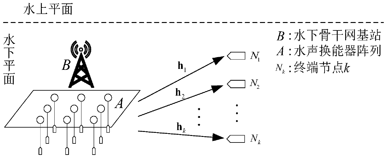
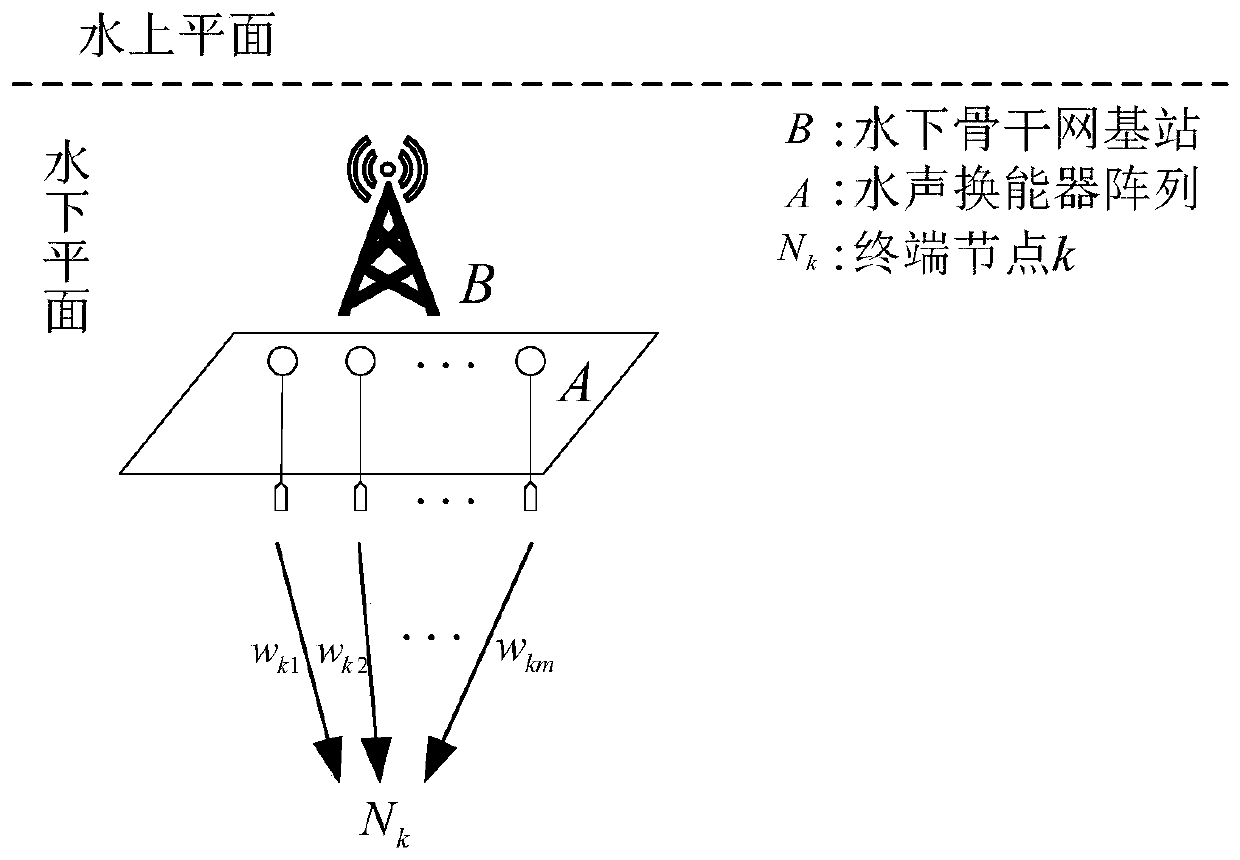
[0063] The schematic diagram of the underwater acoustic communication system and the schematic diagram of the beamforming of the base station in the embodiment of the present invention are as follows figure 1 , 2 shown.

[0064] The schematic diagram of the transmitter device of the underwater base station is as follows: Figure 5 As shown, it is composed of an underwater acoustic transducer array, a multi-channel data acquisition module, a base station main control module, a weight matrix adjustment module, and a beamforming module. The underwater backbone network base station uses its underwater acoustic transducer array to broadcast signals. The multi-channel data acquisition module collects the received signals of the underwater acoustic transducer array in real time and sends them to the base station main control module for monitoring. The base station main control module obtains the beamforming matrix The optimal value of W * And sent to the weight matrix adjustment m...


PUM


Abstract

Disclosed in the present invention are a resource allocation method and a device of an underwater acoustic communication system having wireless energy collection capability. In said method, an underwater acoustic transducer array is provided at a backbone network base station or a central node, and a weight matrix of the underwater acoustic transducer array of the base station is optimized by means of a beamforming technology, so that an underwater acoustic signal emitted by the base station is aligned with an underwater terminal node. After an acoustic wave signal received by the underwater terminal node is converted into an electrical signal by means of the underwater acoustic transducer, a power splitter is used to separate the electrical signal into two paths of signal flows, one path of signal performing signal detection, and the other path of signal performing energy collection by means of an energy collection module, and the collected energy charges a battery of the terminal node by means of a power supply module, thereby achieving energy supplement of the terminal node. Said method obtains the maximum energy collection of a terminal node while ensuring the communication quality, thereby performing energy supplement to the terminal node of the underwater acoustic communication network to the maximum extent.

Description

technical field [0001] The invention relates to the technical field of underwater acoustic communication, in particular to a resource allocation method and device for an underwater acoustic communication system with wireless energy collection capability. Background technique [0002] Underwater acoustic communication is the mainstream technology of underwater communication. Since the advent of underwater acoustic communication technology, it has been facing problems such as extended communication time, narrow available bandwidth, severe signal attenuation, and difficulties in energy supplementation for underwater node equipment. [0003] Due to the particularity of underwater and marine environments, underwater acoustic communication network nodes are usually powered by batteries with very limited energy, and the life cycle of the network is limited by the battery energy of the nodes; and the maintenance of underwater acoustic communication network nodes is particularly diff...

Claims


Application Information

Patent Timeline
IPC IPC(8): H04B13/02H04W16/28H04W24/02H02J50/00
CPCH02J50/00H04B13/02H04W16/28H04W24/02
Inventor 冯义志袁添文张军宁更新季飞
Owner SOUTH CHINA UNIV OF TECH
Why Eureka
Try Eureka