
Cathode plates, bipolar plates, fuel cell stacks, powertrains and vehicles

A fuel cell and cathode plate technology, applied in fuel cells, fuel cell groups, circuits, etc., can solve the problems of increasing mass transfer capacity, increasing flow resistance, large flow pressure drop, etc., to achieve enhanced diffusion, increased flow resistance, The effect of reducing the angle

Active Publication Date: 2021-07-23
GREE ELECTRIC APPLIANCES INC
View PDF5 Cites 0 Cited by
  • Summary
  • Abstract
  • Description
  • Claims
  • Application Information

AI Technical Summary

Problems solved by technology

In the existing fuel cell configuration, the mass transfer capacity of the reaction gas is generally poor in the channel with better flow rate, which easily causes concentration polarization on the electrode; and by increasing the geometric complexity of the reaction gas channel (such as increasing The method of increasing the mass transfer capacity of the turbulence structure) significantly increases the flow resistance, often resulting in a large flow pressure drop, which is very likely to outweigh the gain, resulting in a decrease in the net output power of the fuel cell

Method used


Image

  • Cathode plates, bipolar plates, fuel cell stacks, powertrains and vehicles
  • Cathode plates, bipolar plates, fuel cell stacks, powertrains and vehicles
  • Cathode plates, bipolar plates, fuel cell stacks, powertrains and vehicles

Examples


no. 1 example

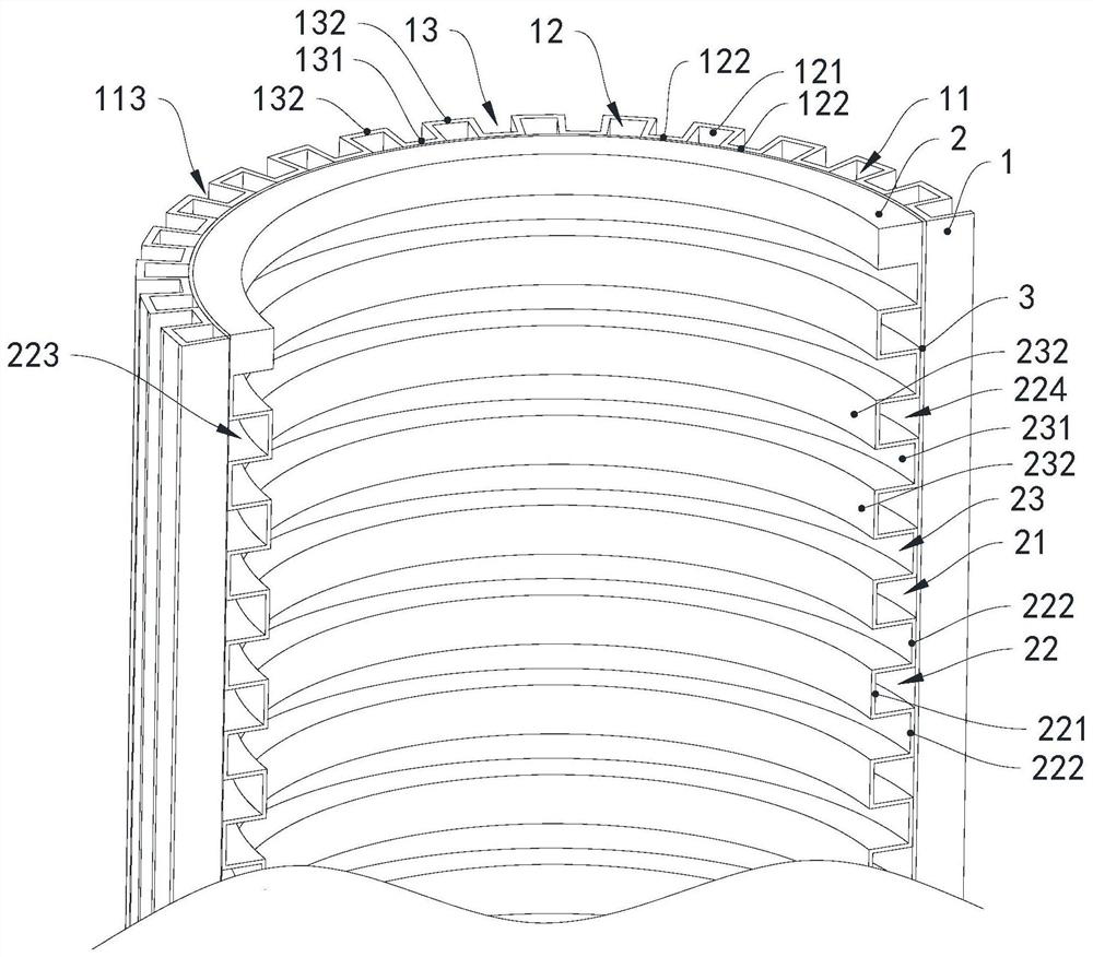
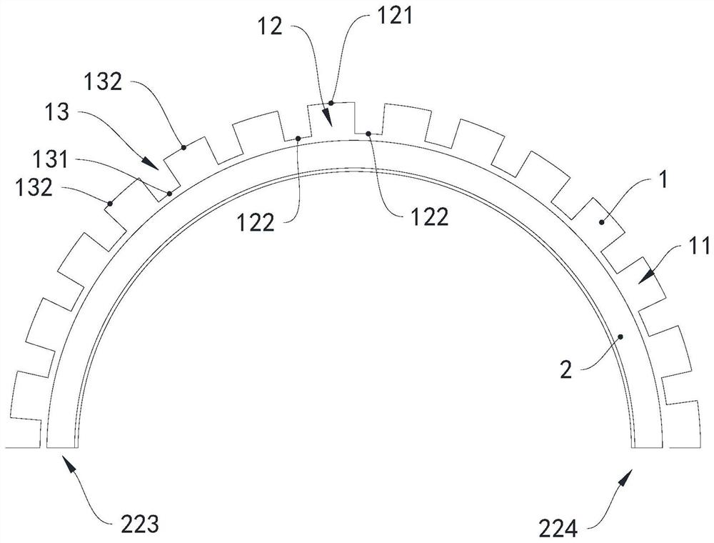
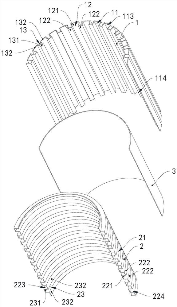
[0044] see Figure 1 to Figure 4 , the fuel cell of this embodiment includes a membrane electrode 3 and a bipolar plate, the bipolar plate includes an anode plate 1 and a cathode plate 2, the membrane electrode 3 is located between the anode plate 1 and the cathode plate 2, and the anode plate 1, the membrane electrode 3 It is arranged in close contact with the cathode plate 2. Both the cathode plate 2 and the anode plate 1 are made of metal materials, and both the cathode plate 2 and the anode plate 1 are formed by stamping.

[0045]The cathode plate 2 is an arc whose central angle is a flat angle, and the axial direction of the cathode plate 2 extends along the vertical direction. The cathode plate 2 is provided with a cathode gas flow field 21, and the cathode gas flow field 21 includes a cathode air intake main channel (not shown Shown), the cathode gas outlet main channel (not shown) and a plurality of cathode gas sub-channels 22, the first ends of the plurality of catho...

no. 4 example

[0064] As the description of the fourth embodiment of the cathode plate and bipolar plate of the fuel cell of the present invention, only the differences from the first embodiment of the cathode plate and bipolar plate of the fuel cell described above will be described below.

[0065] see Figure 7 , the cathode plate 7 and the anode plate 8 are arcs whose central angle is the peripheral angle, that is, circular.


PUM


Abstract

The invention provides a cathode plate, a bipolar plate, a fuel cell stack, a power assembly and a vehicle. The cathode plate is arc-shaped, and a cathode gas flow field is arranged on the cathode plate, and the cathode gas flow field includes a plurality of cathode gas shunts. The cathode gas distribution channel is located on the peripheral wall of the cathode plate, the cathode gas distribution channel includes a first air inlet and a first gas outlet, a plurality of first air inlets are arranged along the axial direction of the cathode plate, and a plurality of first outlets The gas ports are arranged along the axial direction of the cathode plate. A first cooling water channel is opened on the side of the cathode plate opposite to the cathode gas flow field. The cathode plate of the fuel cell of the present invention can increase the mass transfer capacity of the reactant gas without significantly increasing the flow resistance.

Description

technical field [0001] The invention relates to the technical field of fuel cells, in particular to a cathode plate and a bipolar plate of a fuel cell, a fuel cell stack, a power assembly and a vehicle. Background technique [0002] A fuel cell is an energy converter that directly converts the chemical energy of "fuel gas" into direct current electrical energy. Under the current severe energy and environmental situation, hydrogen energy, as a high-quality, efficient and clean energy material, has gradually attracted people's attention. At the same time, fuel cells, as one of the important forms of hydrogen energy utilization, have also attracted the pouring of many scientific research and industrial forces. In the case of a hydrogen-oxygen fuel cell, the products are water and heat. The core components contained inside the fuel cell include membrane electrodes and plates. During the working process, the membrane electrode should maintain a certain water content, so that t...

Claims


Application Information

Patent Timeline
Patent Type & Authority Patents(China)
IPC IPC(8): H01M8/0258H01M8/0267H01M8/24
CPCH01M8/0258H01M8/0267H01M8/24Y02E60/50
Inventor 谭建明肖彪张永
Owner GREE ELECTRIC APPLIANCES INC
Learn More