
Middle-arranged double-axial-flow centrifugal fan

A technology of centrifugal fan and axial fan, which is applied to axial flow pumps, pump devices, mechanical equipment, etc., can solve the problems of affecting the performance of the air duct, occupying the air intake area of ​​the air duct, and serious homogeneity, etc., to achieve increased smoke collection The effect of increasing the range, increasing the negative pressure area, and improving the effective utilization rate

Pending Publication Date: 2019-08-16
HANGZHOU ROBAM APPLIANCES CO LTD
View PDF0 Cites 2 Cited by
  • Summary
  • Abstract
  • Description
  • Claims
  • Application Information

AI Technical Summary

Problems solved by technology

The structure of this kind of fan is basically the same among all manufacturers, and the homogeneity is serious, and the motor is fixed on one side of the air duct, occupying the air inlet area on one side of the air duct, which seriously affects the performance of the air duct

Method used


Image

  • Middle-arranged double-axial-flow centrifugal fan
  • Middle-arranged double-axial-flow centrifugal fan

Examples


Embodiment 1

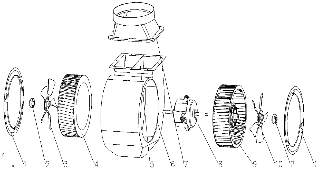
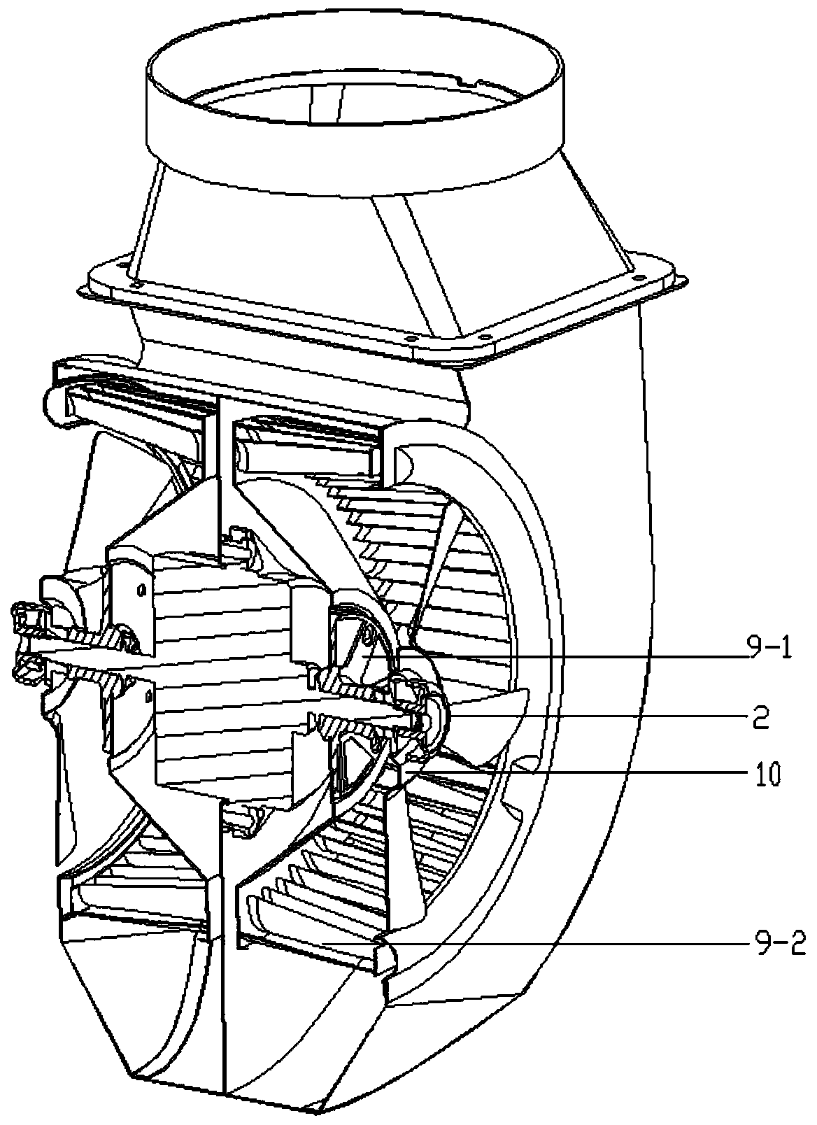
[0024] Such as figure 1 , figure 2 As shown, a central dual-axial flow centrifugal fan includes a dual output shaft motor 8, an air duct 6, a centrifugal impeller and a fan, and the dual output shaft motor 8 is arranged at the central position of the air inlet of the air duct 6, The centrifugal impeller and the fan are respectively arranged in sequence along the direction of the output shafts on both sides of the double output shaft motor 8 .

[0025] In the above example, the present invention sets a central double-axial flow centrifugal fan, and sets a double-output-shaft motor 8 in the center of the air duct 6. In this example, the double-output-shaft motor 8 adopts an outer rotor motor, which is driven by the motor and installed in the air duct. The 4 left centrifugal impellers, the right centrifugal impellers 9 and the fan on both sides of the motor in the air inlet of 6 realize uniform air intake at the air inlets on both sides of the air duct 6, reducing the influence...

Embodiment 2

[0032] A central dual-axial flow centrifugal fan, including a dual-output shaft motor 8, an air duct 6, a centrifugal impeller and a fan, the dual-output shaft motor 8 is arranged at the central position of the air inlet of the air duct 6, along the dual-output The direction of the output shaft on both sides of the shaft motor 8 is respectively provided with a centrifugal impeller and a fan in sequence, wherein, the disc of the centrifugal impeller is provided with four fan blades along the radial direction, and the fan blades are arranged along the dual output The output shaft of the shaft motor 8 extends toward the outside of the air inlet of the air duct.

[0033] In this embodiment, the fan and the centrifugal impeller are integrated. When the fan is working, the blades on the disc of the centrifugal impeller rotate to form a negative pressure area in the air inlets on both sides of the air duct 6, and are connected to the outer edge of the disc of the centrifugal impeller....


PUM


Abstract

The invention discloses a middle-arranged double-axial-flow centrifugal fan. The centrifugal fan comprises a double-output shaft motor, an air duct, centrifugal impellers and fans, wherein the double-output shaft motor is arranged at the central position of an air inlet of the air duct, and the centrifugal impellers and the fans which rotate coaxially are arranged in the output shaft directions atthe two sides of the double-output shaft motor in sequence. According to the centrifugal fan, the double-shaft motor, the impellers and the fans which are arranged in the middle of the air duct are matched with any other to enable air entering of two sides of the air duct to be uniform.

Description

technical field [0001] The invention relates to the field of range hood fans, in particular to a centrally mounted double-axial flow centrifugal fan. Background technique [0002] In the prior art, the fans currently used in range hoods are basically forward multi-blade centrifugal fans. The motor is fixed on one side of the air duct, the impeller is set on the motor shaft, and the impeller is driven by the motor to rotate. The impeller does work on the gas to make the gas obtain energy (Static pressure and kinetic energy), the airflow enters the impeller along the axial direction and is turned by the action of the centrifugal fan, and the airflow is discharged through the outlet of the fan in the radial direction under the action of centrifugal force. The structure of this kind of fan is basically the same among all manufacturers, and the homogeneity is serious, and the motor is fixed on one side of the air duct, occupying the air inlet area on one side of the air duct, whi...

Claims


Application Information

Patent Timeline
IPC IPC(8): F04D25/06F04D25/16F04D17/16F04D19/00F04D29/40F04D29/28F04D29/32
CPCF04D25/06F04D25/166F04D17/16F04D19/002F04D29/403F04D29/283F04D29/325
Inventor 任富佳郑桐福孟君唐人罗贤才余国成周海昕
Owner HANGZHOU ROBAM APPLIANCES CO LTD
Learn More