A kind of electroplating equipment

A technology of electroplating equipment and conductive shafts, applied in the direction of electrolytic components, electrolytic processes, cells, etc., can solve the problems of multiple defects in electroplating, poor structural design, inconvenient movement, etc., and achieve the effect of simple equipment structure and efficient electroplating process

Active Publication Date: 2021-03-26
兰溪龙升装饰工艺品有限公司
View PDF13 Cites 0 Cited by
  • Summary
  • Abstract
  • Description
  • Claims
  • Application Information

AI Technical Summary

Problems solved by technology

[0002] When the electroplating equipment is working, it is often necessary to connect the workpiece to the circuit power supply, to form a complete circuit between the workpiece, the plated metal and the circuit, and to use the current to electroplate the plated metal to the workpiece. The conversion of multiple processes not only needs to transport the workpiece to different reaction pools, but also needs to quickly dry the workpiece. During this process, due to the poor insulation performance of some parts hanging the workpiece, there are more defects in the electroplating. And because it is relatively inconvenient when the workpiece is moved, the work efficiency of the personnel is greatly reduced, while the process effect of electroplating is reduced, the convenience for the personnel to work is greatly reduced, and the existing suspension of the workpiece is zero. Due to the poor structural design of the parts, it is difficult to hang and process some large batches of larger parts, which greatly reduces the working efficiency of the equipment and greatly reduces the convenience of the equipment during use.

Method used


Image

  • A kind of electroplating equipment
  • A kind of electroplating equipment
  • A kind of electroplating equipment

Examples


Embodiment Construction

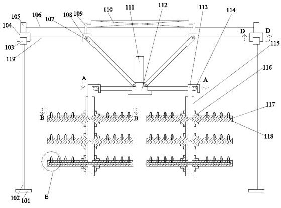
[0022] Such as Figure 1-Figure 6 As shown, the present invention is described in detail. For the convenience of description, the orientations mentioned below are now stipulated as follows: figure 1 The up, down, left, right, front and back directions of the projection relationship are consistent. A kind of electroplating equipment of the present invention includes a fixed rod 119. The left and right ends of the fixed rod 119 are fixed with left and right symmetrical sliders 104. Top blocks 105, connecting rods 106 are fixed between the top blocks 105, cylinders 110 are fixed on the upper surface of the connecting rods 106, and a lift that moves under the drive of the cylinders 110 is provided on the outside of the fixed rods 119. device, the lower side of the lifting device is provided with a suspension device for suspending workpieces, and the lower side of the slider 104 is provided with a supporting sliding device for supporting the slider 104 .

[0023] Beneficially, whe...


PUM


Abstract

The invention discloses electroplating equipment. The electroplating equipment comprises a fixed rod, left and right symmetric sliding blocks are fixedly arranged on the left end surface and the rightend surface of the fixed rod, a top block is fixedly arranged on the upper end surface of each sliding block, and a connecting rod is fixedly arranged between the top blocks; and an air cylinder is fixedly arranged on the upper end surface of the connecting rod, a lifting device capable of moving under the driving of the air cylinder is arranged on the outer side of the fixed rod, a hanging device used for hanging a workpiece is arranged on the lower side of the lifting device, and the lower side of each sliding block is provided with a supporting sliding device for supporting each sliding block. According to the electroplating equipment, the structure is simple, and the lifting device, the hanging device and the supporting sliding devices are adopted, so that the equipment can efficiently move above an appointed electrolytic tank under the use of the personnel, and rapid moving and transferring can be carried out; and the structural design of the internal insulation and waterproofingof the equipment and the function of suspending the workpiece in multiple layers greatly increase the practical life and practicability of the equipment, and the use reliability and safety of the equipment are greatly improved.

Description

technical field [0001] The invention relates to the technical field of electroplating equipment, in particular to electroplating equipment. Background technique [0002] When the electroplating equipment is working, it is often necessary to connect the workpiece to the circuit power supply, to form a complete circuit between the workpiece, the plated metal and the circuit, and to use the current to electroplate the plated metal to the workpiece. The conversion of multiple processes not only needs to transport the workpiece to different reaction pools, but also needs to quickly dry the workpiece. During this process, due to the poor insulation performance of some parts hanging the workpiece, there are more defects in the electroplating. And because it is relatively inconvenient when the workpiece is moved, the work efficiency of the personnel is greatly reduced, while the process effect of electroplating is reduced, the convenience for the personnel to work is greatly reduced...

Claims


Application Information

Patent Timeline
Patent Type & Authority Patents(China)
IPC IPC(8): C25D17/00C25D21/10C25D19/00
CPCC25D17/00C25D21/10
Inventor 不公告发明人
Owner 兰溪龙升装饰工艺品有限公司
Why Eureka
Try Eureka