latch assembly

A technology of latches and components, applied to vehicle parts, transmissions, vehicle springs, etc., can solve problems such as high energy consumption and slow response time, achieve low production costs, prevent unintentional movement, and simple design effects

Active Publication Date: 2020-11-27
BEIJING WEST IND CO LTD
View PDF4 Cites 0 Cited by
  • Summary
  • Abstract
  • Description
  • Claims
  • Application Information

AI Technical Summary

Problems solved by technology

However, the electromagnetic activation mechanism requires power input for the locking / unlocking of the solenoid valve, which has a slow response time and high energy consumption

Method used


Image

  • latch assembly
  • latch assembly
  • latch assembly

Examples


Embodiment Construction

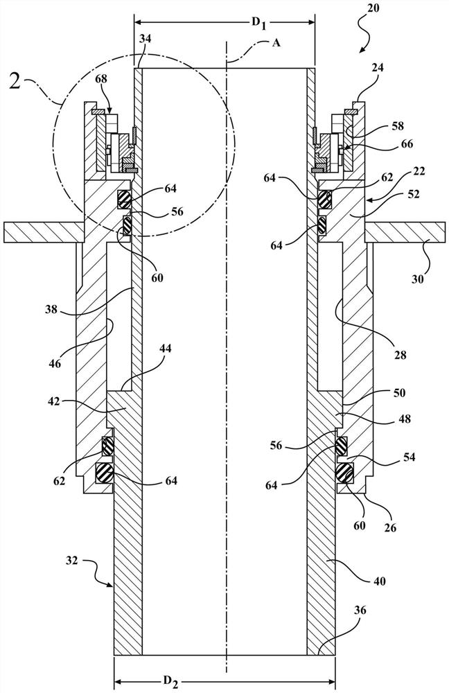
[0014] Referring to the drawings, wherein like reference numerals indicate corresponding parts throughout the several views, figure 1 A latch assembly 20 constructed in accordance with one embodiment of the present invention is generally shown in . Typically, the latch assembly 20 is used in vehicles to raise and lower the height of the vehicle.

[0015] refer to figure 1 The latch assembly 20 includes a lift housing 22 having a generally tubular shape annularly disposed about a central axis A and extending along the central axis A between a first open end 24 and a second open end 26 . Lift housing 22 defines a chamber 28 extending between first open end 24 and second open end 26 . A lift spring seat 30 is disposed about the first open end 24 , is attached to the lift housing 22 , and extends annularly about the central axis A. As shown in FIG. A support tube 32 having a generally cylindrical shape is slidably disposed in the chamber 28 . The support tube 32 is disposed in...


PUM


Abstract

The invention provides a latch assembly. The latch assembly includes a lift housing extending along a central axis between a first open end and a second open end and defining a chamber extending between the first open end and the second open end. A support tube is arranged in the chamber and extends between a first end and a second end. A moving member is arranged between the support tube and thelift housing and used for moving the lift housing between an extended position and a lowered position. The moving member includes an inner ring and an outer ring. The inner ring extends around the support tube. The outer ring is attached to the lift housing and used for converting axial movement of the support tube into rotational movement. A plurality of engagement members are located between theinner ring and the outer ring and used for axially moving the inner ring and the outer ring along the central axis between the extended position and the lowered position.

Description

technical field [0001] The present invention generally relates to a latch assembly for raising and lowering the height of a vehicle. Background technique [0002] Devices for adjusting the height of the vehicle body are known. These devices can be arranged in the suspension struts of the motor vehicle, in particular for increasing the ground clearance of the motor vehicle or for lowering the bodywork on flat road surfaces. Typically, such devices comprise a lift housing, arranged on a central axis, defining a chamber. A support tube is disposed in the chamber, and the lifting housing is movable along the central axis relative to the support tube. Movement of the lifting housing is typically performed using hydraulic actuation. However, constant hydraulic pressure is required if it is desired to keep the lift housing in the extended position to increase the height of the vehicle. Therefore, the hydraulic pump needs to be operated / restarted periodically due to inevitable i...

Claims


Application Information

Patent Timeline
Patent Type & Authority Patents(China)
IPC IPC(8): B60G17/08
CPCB60G17/08B60G2800/914B60G11/16B60G15/06B60G17/005B60G17/0157B60G17/021B60G2202/42B60G2202/441B60G2500/22B60G2500/30F16H25/2015
Inventor J·P·斯曼斯基
Owner BEIJING WEST IND CO LTD
Why Eureka
Try Eureka