Magnetic optical element holder and microscope assembly including same

A technology of optical components and microscopes, applied in the field of microscopy, can solve problems such as not including

Inactive Publication Date: 2009-07-29
LEICA MICROSYSTEMS CMS GMBH
View PDF5 Cites 0 Cited by
  • Summary
  • Abstract
  • Description
  • Claims
  • Application Information

AI Technical Summary

Problems solved by technology

However, this publication does not include the teaching of magnetically securing the optics within the optical path at the base of the microscope

Method used


Image

  • Magnetic optical element holder and microscope assembly including same
  • Magnetic optical element holder and microscope assembly including same
  • Magnetic optical element holder and microscope assembly including same

Examples


Embodiment Construction

[0026] First of all, it should be understood that the same reference numerals in different drawings represent the same components of the present invention. While the invention has been described in terms of what are presently considered to be the preferred embodiments, it is to be understood that the invention is not limited to the disclosed embodiments.

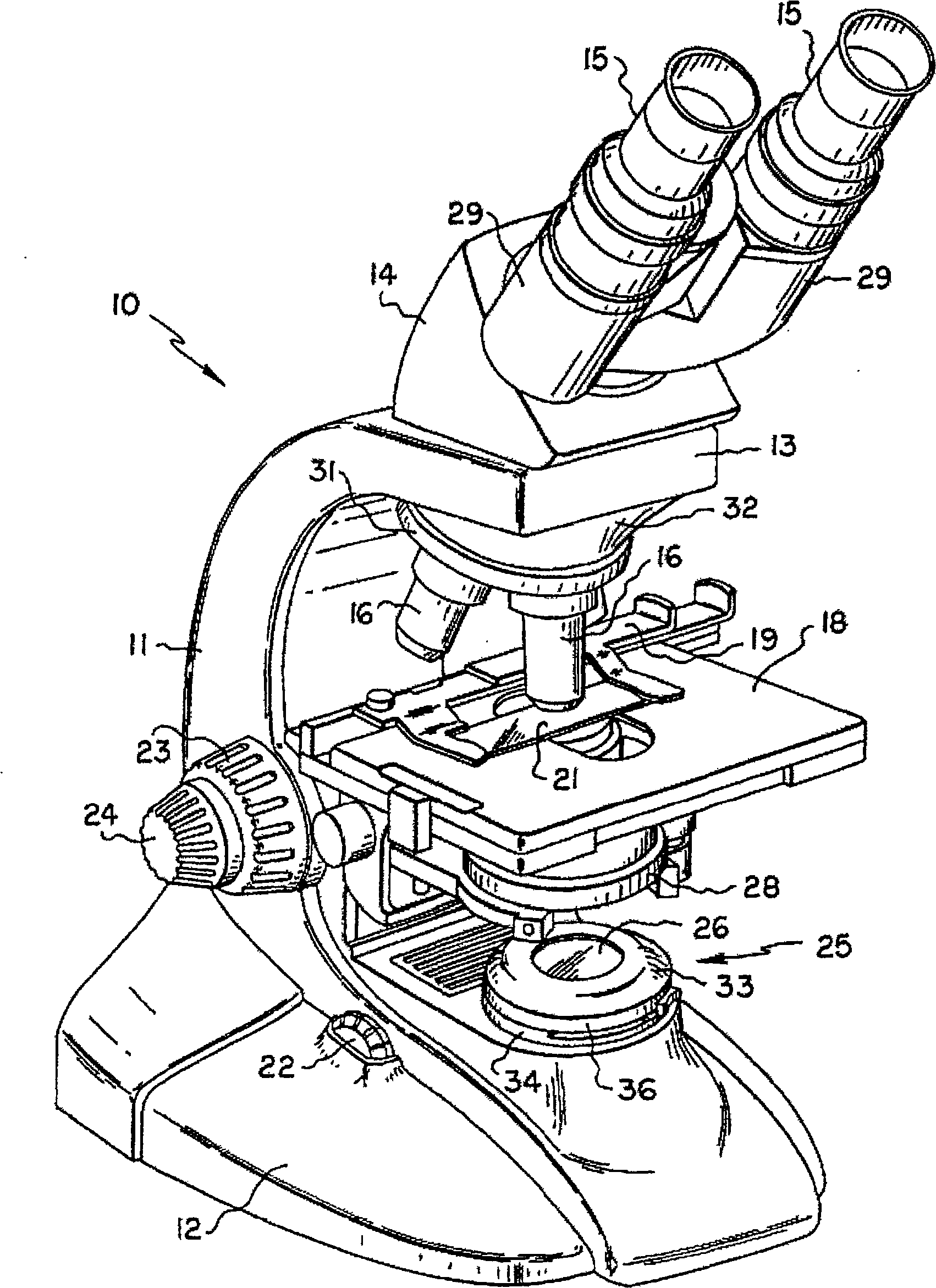
[0027] The present invention broadly includes a microscope apparatus comprising a microscope having an illuminator mounted on a base, an optical element holder operatively configured to hold an optical element within the optical path of the microscope, and a A device that magnetically secures an optic holder to an illuminator. exist figure 1 The perspective view of a conventional compound microscope is shown. While the present invention is applicable to a wide variety of microscopes, as well as other optical instruments, it is beneficial to review the basic microscope construction and function to understand the present inv...


PUM


Abstract

An optical component holder of the present invention includes a housing having a top surface and a bottom surface, the housing having an aperture operatively configured to support an optical component such as a filter or the like, and at least one bottom surface attached to the housing and a magnet extending therefrom, the magnet being effectively arranged to attract a portion of the luminaire mounted to the base. A magnetic optical element holder and microscope optical element combination having an annular housing with a flanged aperture therein, the housing having a top surface and a bottom surface, the optical element operatively configured to be retained in the flanged within the bore, and at least one magnet is attached to the bottom surface of the housing. A magnetic optical element holder and a microscope bottom mounted illuminator, the illuminator having at least some ferromagnetic properties, the optical element holder comprising a housing having an aperture therein configured to support the optical element, and at least one mounted to the housing and A magnet provided to hold the holder to a part of the luminaire.

Description

technical field [0001] The present invention relates generally to microscopy, in particular to microscopes, and more particularly to an optical element holder for a microscope. Background technique [0002] As we all know, a microscope is an optical instrument used to observe, study and analyze small objects. There are many different types of microscopes, each suitable for a particular application. They include compound microscopes, stereo microscopes, confocal microscopes, inverted microscopes, laser microscopes, fluorescence microscopes, and polarizing microscopes, just to name a few. [0003] The present invention generally relates to compound microscopes and microscopes employing the same or similar optical configurations as in conventional compound microscopes. [0004] There are various moving parts commonly used in compound microscopes to provide different types of light to illuminate the object under study. By using different types of light, a larger area can be o...

Claims


Application Information

Patent Timeline
Patent Type & Authority Patents(China)
IPC IPC(8): G02B7/02G02B21/06G02B7/00G02B21/16
CPCG02B21/06G02B7/006
Inventor 拉塞尔·博纳文图拉
Owner LEICA MICROSYSTEMS CMS GMBH
Why Eureka
Try Eureka