
Camera device, electronic equipment and application method of electronic equipment

A technology of a camera device and electronic equipment, applied in the field of camera device and electronic equipment, can solve problems such as affecting the appearance of intelligent electronic products, inconvenient to use, and unable to adjust the position.

Active Publication Date: 2019-08-09
AAC MICROTECH CHANGZHOU
View PDF4 Cites 23 Cited by
  • Summary
  • Abstract
  • Description
  • Claims
  • Application Information

AI Technical Summary

Problems solved by technology

[0005] In order to meet the needs of users, the camera device usually includes a front camera and a rear camera. The rear camera is directly fixed and exposed on the back of the smart electronic product, and the front camera needs to be installed on the non-display area on the front of the smart electronic product. It affects the appearance of smart electronic products, and its position cannot be adjusted, which is inconvenient to use

Method used


Image

  • Camera device, electronic equipment and application method of electronic equipment
  • Camera device, electronic equipment and application method of electronic equipment
  • Camera device, electronic equipment and application method of electronic equipment

Examples


Embodiment Construction

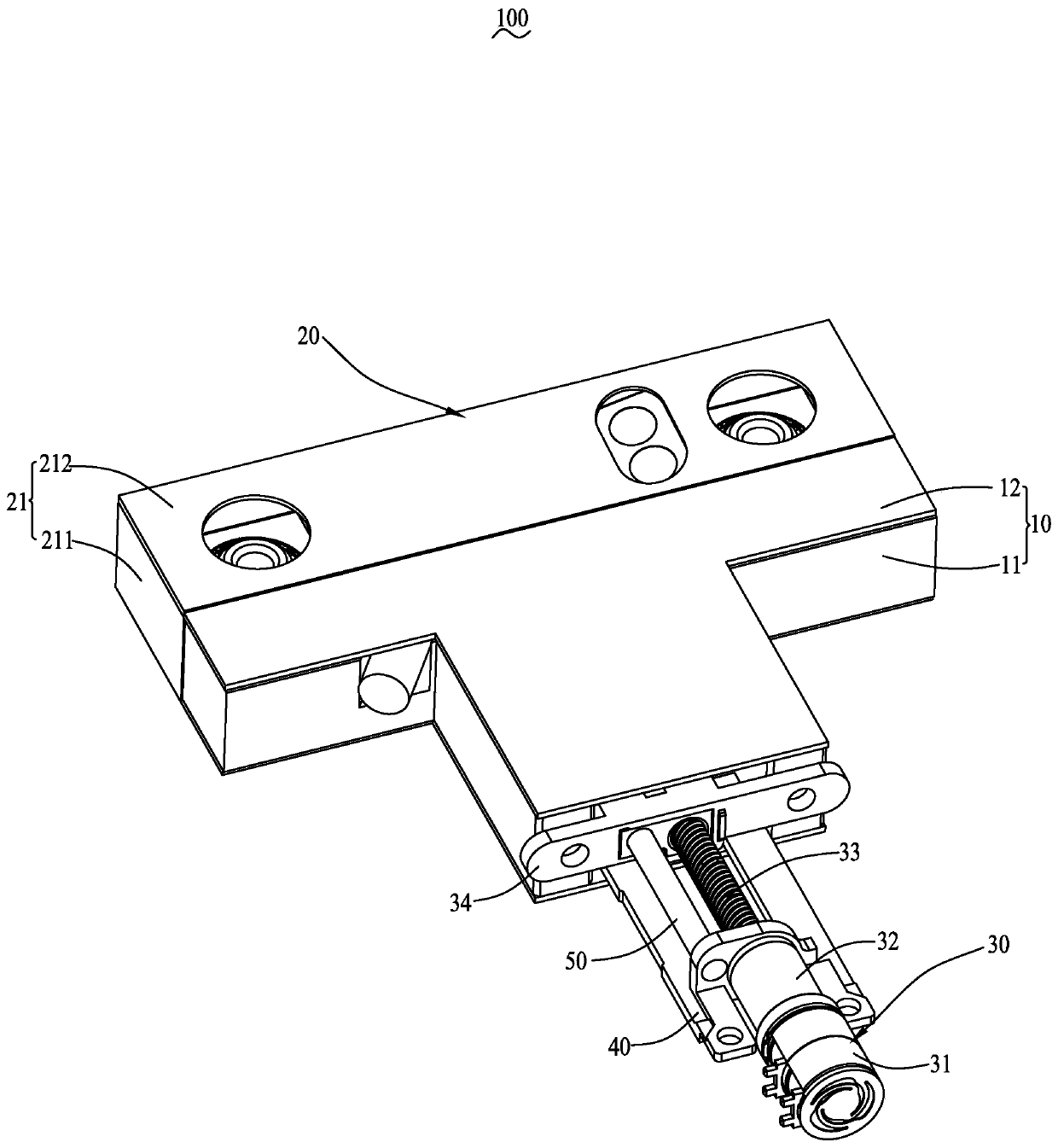
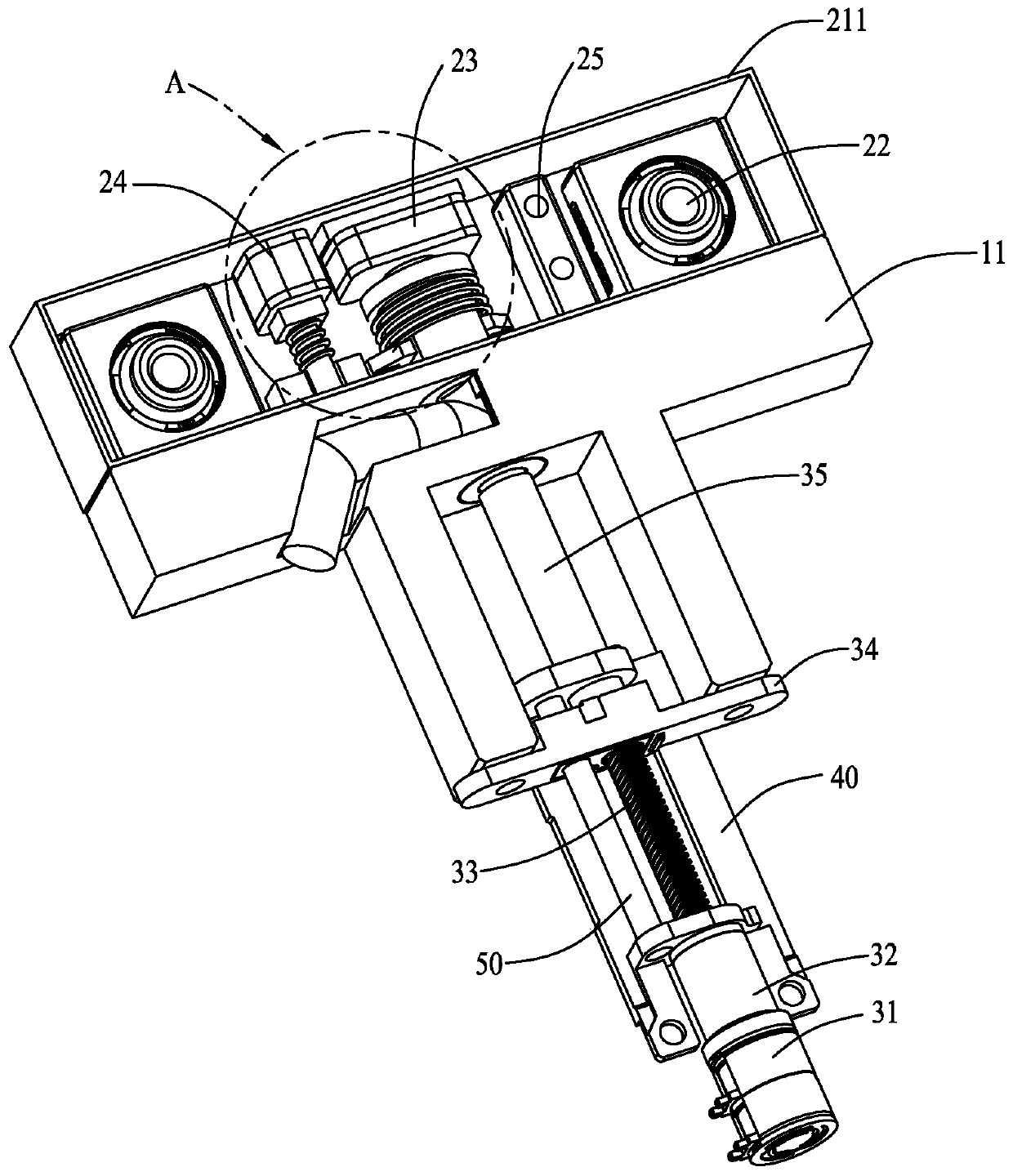
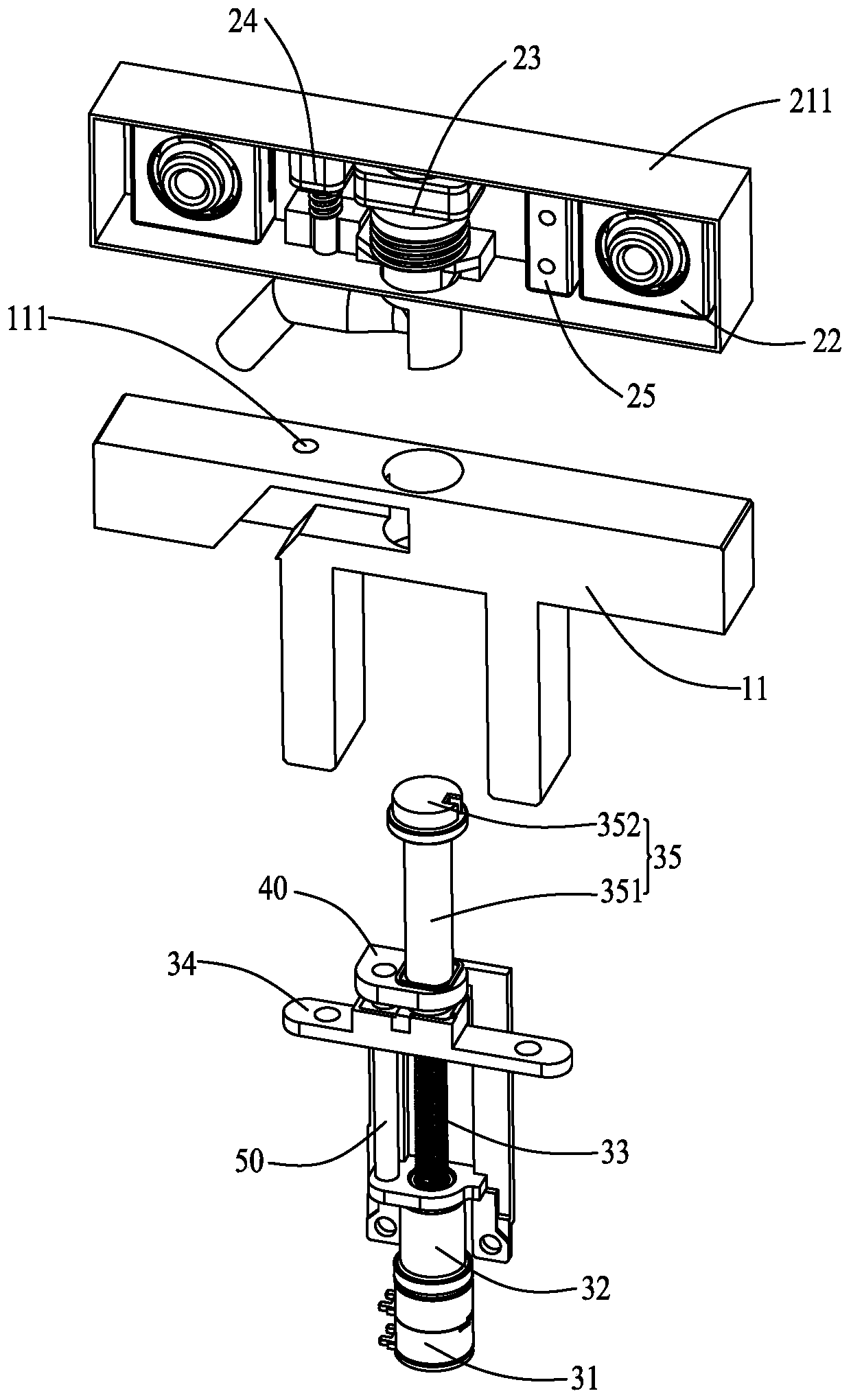
[0037] Combine below Figure 1 to Figure 8 The present invention is described in detail.

[0038] It should be noted that all directional indications (such as up, down, left, right, front, back, inside, outside, top, bottom...) in the embodiments of the present invention are only used to explain As shown in the figure), if the relative positional relationship between the various components, etc., if the specific posture changes, the directional indication will also change accordingly.

[0039] It should also be noted that when an element is referred to as being “fixed” or “disposed on” another element, the element may be directly on the other element or there may be an intervening element at the same time. When an element is referred to as being "connected to" another element, it can be directly connected to the other element or intervening elements may also be present.

[0040] see figure 1 According to an embodiment of the present invention, a camera device 100 is provide...


PUM


Abstract

The invention discloses a camera device, electronic equipment and an application method of the electronic equipment. The camera device comprises a supporting base, a camera mechanism installed on oneside of the supporting base and a driving mechanism installed on the other side of the supporting base. A clamping structure is arranged between the camera mechanism and the supporting mechanism; theclamping structure can selectively clamp or separate the camera mechanism and the supporting base; the camera mechanism comprises a first relay, the first relay comprises a first stator and a rotor capable of moving relative to the first stator; when the camera mechanism is clamped with the supporting base; the rotor of the first relay is separated from the driving mechanism, the driving mechanismcan drive the camera mechanism and the supporting base to do linear motion together, and when the camera mechanism is separated from the supporting base in a clamped mode, the rotor of the first relay is connected with the driving mechanism and driven by the driving mechanism to drive the camera mechanism to rotate relative to the supporting base. The camera device has telescopic and rotary functions, is convenient for a user to use, and meanwhile, enables the appearance of the electronic equipment to be more attractive.

Description

[0001] 【Technical field】 [0002] The present invention relates to the technical field of photographing equipment, in particular to an imaging device, an electronic device using the imaging device, and a method for using the electronic device. [0003] 【Background technique】 [0004] With the advent of the Internet era, the number of smart electronic products continues to increase. The functions of smart electronic products are rich and diverse, and are deeply loved by users. One of them is the shooting function. Therefore, the camera device used for shooting is widely used in In smart electronic products. [0005] In order to meet the needs of users, the camera device usually includes a front camera and a rear camera. The rear camera is directly fixed and exposed on the back of the smart electronic product, and the front camera needs to be installed on the non-display area on the front of the smart electronic product. It affects the appearance of smart electronic products, an...

Claims


Application Information

Patent Timeline
Patent Type & Authority Applications(China)
IPC IPC(8): H04M1/02H04N5/225
CPCH04M1/0264H04M1/026H04M1/0283H04N23/57
Inventor 范婧倪天恒
Owner AAC MICROTECH CHANGZHOU
Learn More