
Serial data transmission circuit

A technology of serial data and transmission circuit, which is applied in the field of serial data transmission circuit, and can solve the problem of uneven display of display devices

Active Publication Date: 2019-08-09
BOE TECH GRP CO LTD
View PDF7 Cites 1 Cited by
  • Summary
  • Abstract
  • Description
  • Claims
  • Application Information

AI Technical Summary

Problems solved by technology

[0003] The embodiment of the present application provides a serial data transmission circuit, which is used to solve the problem of uneven display of the display device caused by the transmission delay of the data transmission circuit in the prior art

Method used


Image

  • Serial data transmission circuit
  • Serial data transmission circuit
  • Serial data transmission circuit

Examples


Embodiment Construction

[0033] In view of the problem of uneven display of the display device caused by the transmission delay of the serial data transmission circuit in the prior art. The embodiment of this application provides the following solutions:

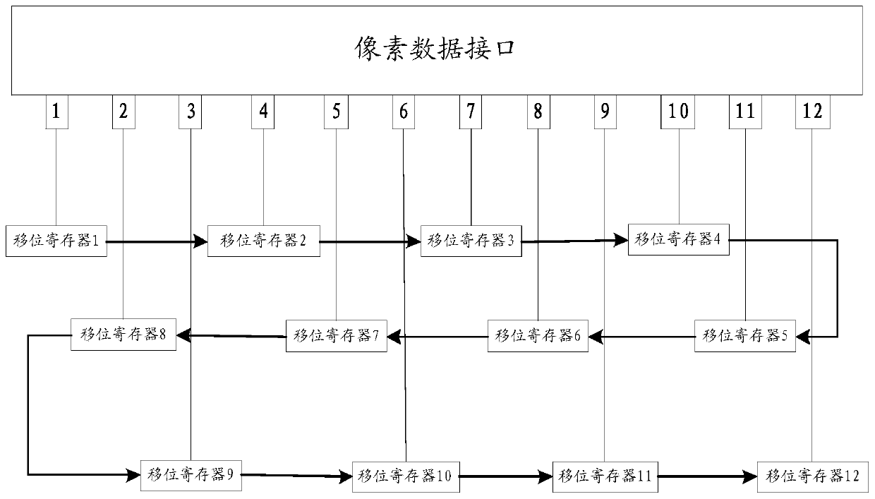
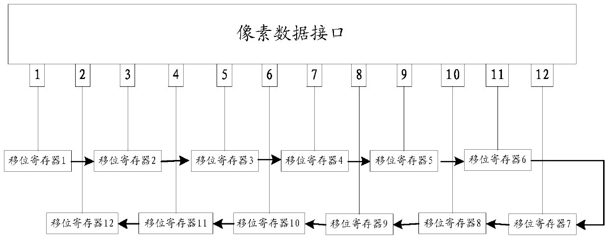
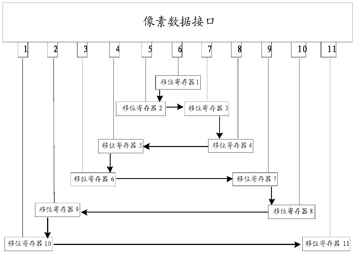
[0034] Specifically, a novel serial data transmission circuit is provided, including:

[0035] Multiple shift registers cascaded in sequence, multiple pixel data interfaces;

[0036] Wherein, the connection order of the shift register and the pixel data interface is different from the physical order of the pixel data interface.

[0037] The data transmission circuit provided by this application can solve the problem of uneven display of the display device caused by the transmission delay of the data transmission circuit in the prior art, and change the data by changing the connection relationship between the shift register and the pixel data interface. The order in which the transmission data is written into the pixels, after dispersing the delays...


PUM


Abstract

The invention discloses a serial data transmission circuit. The serial data transmission circuit comprises a plurality of shift registers and a plurality of pixel data interfaces which are sequentially cascaded, wherein the connection order of the shift registers and the pixel data interfaces is different from the physical order of the pixel data interfaces. By applying the serial data transmission circuit provided by the invention, the problem of non-uniform display of a display device caused by transmission delay of a serial data transmission circuit in the prior art can be solved, so that the display quality is improved.

Description

technical field [0001] The present application relates to the technical field of electronic circuits, in particular to a serial data transmission circuit. Background technique [0002] At present, wearable products are becoming more and more popular. For products with low resolution, in order to improve the compatibility with the system, serial data transmission circuits are generally used. Fabricating the serial data transmission circuit on the display panel can save IC cost, improve system compatibility, and reduce frame size, so it is widely used at present. In the prior art, the serial data transmission circuit transmits data in such a way that under the control of SCLK, the shift register receives data sequentially from left to right, and the data latched in the control latch is sequentially written into the display panel from left to right. Among the sub-pixels corresponding to the pixels, the pixels on the display panel are arranged in columns, and the order of writi...

Claims


Application Information

Patent Timeline
Patent Type & Authority Applications(China)
IPC IPC(8): G09G3/20
CPCG09G3/20G09G2310/0286
Inventor 袁丽君
Owner BOE TECH GRP CO LTD
Learn More