
Compliant Constant Torque Couplings

A constant torque, coupling technology, applied in the direction of couplings, elastic couplings, mechanical equipment, etc., can solve the problems of high noise, inability to buffer vibration, low sealing precision, etc., and achieve the effect of high motion precision

Active Publication Date: 2020-06-05
ANHUI UNIV OF SCI & TECH
View PDF7 Cites 0 Cited by
  • Summary
  • Abstract
  • Description
  • Claims
  • Application Information

AI Technical Summary

Problems solved by technology

However, the rigid coupling does not have the ability of shock absorption, buffering and compensation for the relative displacement of the two axes. It requires strict alignment of the two axes, lubrication, low sealing accuracy, and high noise.
[0005] Flexible couplings can be divided into flexible couplings without elastic elements and flexible couplings with elastic elements. Flexible couplings without elastic elements only have the ability to compensate for the relative displacement of the two axes, but cannot buffer and reduce vibration. The flexible coupling with elastic elements contains elastic elements. In addition to the ability to compensate for the relative displacement of the two axes, it also has the effect of buffering and damping. Component flexible couplings can only be installed in high-speed and low-torque occasions

Method used


Image

  • Compliant Constant Torque Couplings
  • Compliant Constant Torque Couplings
  • Compliant Constant Torque Couplings

Examples


Embodiment Construction

[0019] The present invention will be further described in detail below in conjunction with the accompanying drawings.

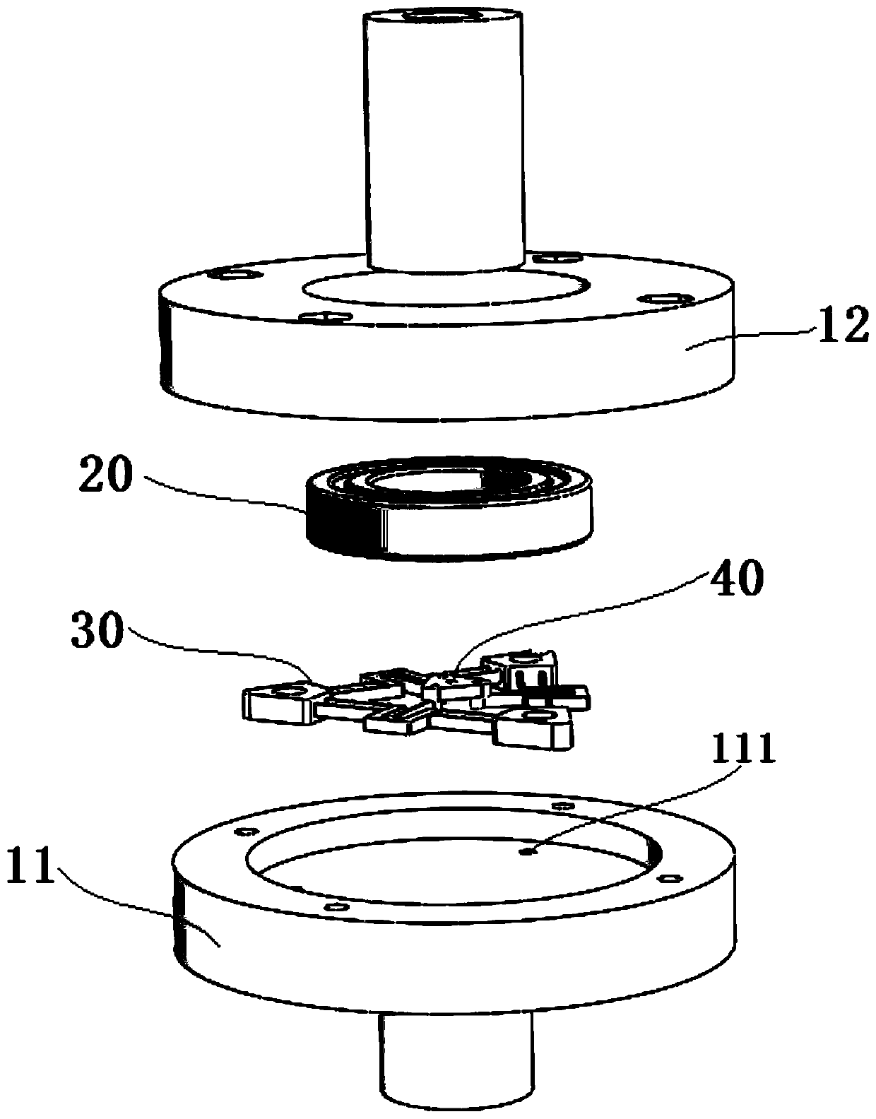
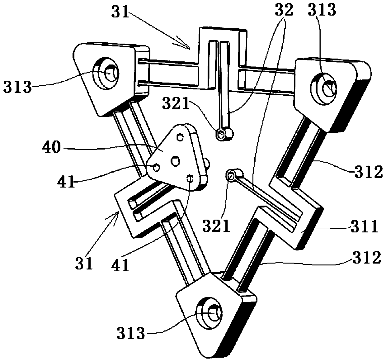
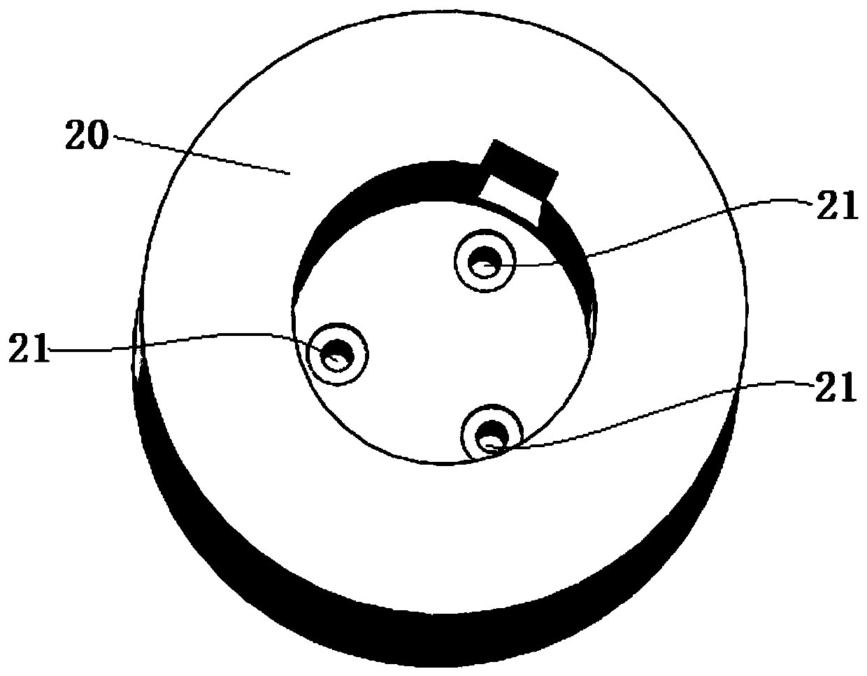
[0020] A compliant constant moment coupling, including first and second half-shells 11 and 12 that are fixedly fitted, the middle part of the first half-shell 11 is fixedly connected with the driving shaft, and the middle part of the second half-shell 12 is connected to the driven shaft sleeve through a bearing The cylinder 20 constitutes a rotational fit. A compliant constant moment mechanism is arranged between the first and second half shells 11 and 12. The compliant constant moment mechanism includes a flexible connected active bracket 30 and a driven bracket 40. The active bracket 30 is fixed on the first On the half shell 11 , the driven bracket 40 is fixedly connected with the inner end of the driven shaft sleeve 20 . In the present invention, a compliant constant moment mechanism is provided in the coupling housing, and the flexible connection between...


PUM


Abstract

The invention discloses a compliant constant-torque coupling. The compliant constant-torque coupling comprises a first half shell and a second half shell, wherein the first half shell and the second half shell are in fixed fit. The middle of the first half shell is fixedly connected with a driving shaft, and the middle of the second half shell and a driven shaft sleeve are in rotary fit through abearing. A compliant constant-torque mechanism is arranged between the first half shell and the second half shell and comprises a driving support and a driven support which are flexibly connected. Thedriving support is fixed to the first half shell, and the driven support is fixedly connected with the inner end of the driven shaft sleeve. According to the above scheme, through the arrangement ofthe compliant constant-torque mechanism, power transmission is achieved between the driving shaft and a driven shaft through elastic deformation between the driving support and the driven support, nofriction is generated on a motion pair, motion precision is high, large torque can be transmitted, and the function of shock absorption can also be achieved.

Description

technical field [0001] The invention relates to the technical field of shaft couplings, and specifically designs a compliant constant moment shaft coupling. Background technique [0002] Coupling refers to a device that connects two shafts or shafts and rotating parts, and rotates together during the transmission of motion and power, and does not disengage under normal conditions. The coupling is composed of the driving shaft connecting part and the driven shaft connecting part, and its working reliability directly affects the performance of mechanical transmission. [0003] Existing couplings can be divided into two categories: rigid couplings and flexible couplings. [0004] The rigid coupling has simple structure, low manufacturing cost, convenient disassembly and maintenance, and can ensure high alignment of the two shafts, large transmission torque, and wide application. However, the rigid coupling does not have the ability of shock absorption, buffering and compensat...

Claims


Application Information

Patent Timeline
Patent Type & Authority Patents(China)
IPC IPC(8): F16D3/56
CPCF16D3/56
Inventor 李保坤刘爱明韩迎鸽张玉玺刘坤张凯
Owner ANHUI UNIV OF SCI & TECH
Learn More