
Gas-distribution assembly and engine

A component and gas distribution technology, which is applied in the direction of engine components, machines/engines, mechanical equipment, etc., can solve the problems that affect the service life of the gas distribution mechanism, the relative sliding between the cylindrical roller and the cam, fatigue wear, etc., and achieve a stable transmission ratio , Reduce relative sliding, reduce fatigue wear effect

Pending Publication Date: 2019-08-09
昆山三一动力有限公司
View PDF0 Cites 0 Cited by
  • Summary
  • Abstract
  • Description
  • Claims
  • Application Information

AI Technical Summary

Problems solved by technology

[0002] At present, in the related art, the rocker arm in the engine gas distribution mechanism is arranged on the rocker arm roller, and the rocker arm roller is a cylindrical roller, and the cylindrical roller cooperates with the cam, and the cam rotates, thereby driving the swing rocker arm to swing; There is a line contact between the cylindrical roller and the cam, and the relative sliding between the cylindrical roller and the cam is easy to cause fatigue wear in the contact area between the cylindrical roller and the cam, which in turn affects the service life of the valve train

Method used


Image

  • Gas-distribution assembly and engine

Examples


Embodiment Construction

[0035] In order to understand the above-mentioned purpose, features and advantages of the present invention more clearly, the present invention will be further described in detail below in conjunction with the accompanying drawings and specific embodiments. It should be noted that, in the case of no conflict, the embodiments of the present application and the features in the embodiments can be combined with each other.

[0036] In the following description, many specific details are set forth in order to fully understand the present invention. However, the present invention can also be implemented in other ways different from this description. Therefore, the protection scope of the present invention is not limited by the specific implementation disclosed below. Example limitations.

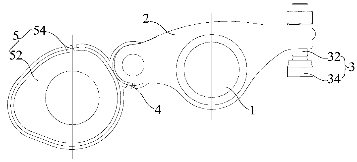
[0037] Refer below figure 1 A gas distribution assembly and an engine according to some embodiments of the present invention are described.

[0038] In the embodiment of the first aspect of the ...


PUM


Abstract

The invention provides a gas-distribution assembly and an engine. The gas-distribution assembly comprises a rotating shaft, a swinging rocker arm, a blocking assembly, a rocker arm rolling wheel and adriving wheel; the swinging rocker arm is rotationally arranged on the rotating shaft in a sleeving mode; the blocking assembly is connected with one end of the swinging rocker arm; the rocker arm rolling wheel is rotationally connected with the other end of the swinging rocker arm; and the driving wheel comprises a cam and a plurality of teeth, the multiple teeth are arranged in the circumferential direction of the cam, the rocker arm rolling wheel is a cylindrical gear, and the driving wheel meshes with the rocker arm rolling wheel. According to the gas-distribution assembly, the teeth arranged in the circumferential direction of the cam drive the rocker arm rolling wheel to rotate, so that the outer surface of the cam does not make direct contact with the smooth cylindrical rolling wheel any more, relative sliding between the cam and the rocker arm rolling wheel is reduced, thus fatigue abrasion caused by friction is reduced, and the service life of the gas-distribution assembly isprolonged; and the cam drives the rocker arm rolling wheel to rotate through the teeth, so that the transmission ratio of the cam to the rocker arm rolling wheel is more stable, and thus the gas-distribution assembly is conveniently controlled for exhaust.

Description

technical field [0001] The invention relates to the technical field of engines, in particular to an air distribution assembly and an engine. Background technique [0002] At present, in the related art, the rocker arm in the engine gas distribution mechanism is arranged on the rocker arm roller, and the rocker arm roller is a cylindrical roller, and the cylindrical roller cooperates with the cam, and the cam rotates, thereby driving the swing rocker arm to swing; There is a line contact between the cylindrical roller and the cam, and the relative sliding between the cylindrical roller and the cam is easy to cause fatigue wear in the contact area between the cylindrical roller and the cam, which in turn affects the service life of the valve train. Contents of the invention [0003] The present invention aims to solve at least one of the technical problems existing in the prior art or related art. [0004] To this end, a first aspect of the invention proposes a gas distribu...

Claims


Application Information

Patent Timeline
Patent Type & Authority Applications(China)
IPC IPC(8): F01L1/08F01L1/18
CPCF01L1/08F01L1/181
Inventor 张辉钱汉生罗亚刚
Owner 昆山三一动力有限公司
Learn More