Conductor winding rod

A technology of conductor winding and winding, applied in the shape/style/structure of winding insulation, shape/style/structure of winding conductors, etc., which can solve problems such as high cost and complicated process

Inactive Publication Date: 2003-02-05
ALSTOM (SWITZERLAND) LTD
View PDF4 Cites 0 Cited by
  • Summary
  • Abstract
  • Description
  • Claims
  • Application Information

AI Technical Summary

Problems solved by technology

However, it is very difficult to produce a flat surface on the narrow side of the conductor by the known process, and in addition, the process of forming and / or subsequent processing of the filling layer with defined rounded corners on the conductor edge is relatively complicated and expensive, Because it is required to be uniform everywhere

Method used


Image

  • Conductor winding rod
  • Conductor winding rod
  • Conductor winding rod

Examples


Embodiment Construction

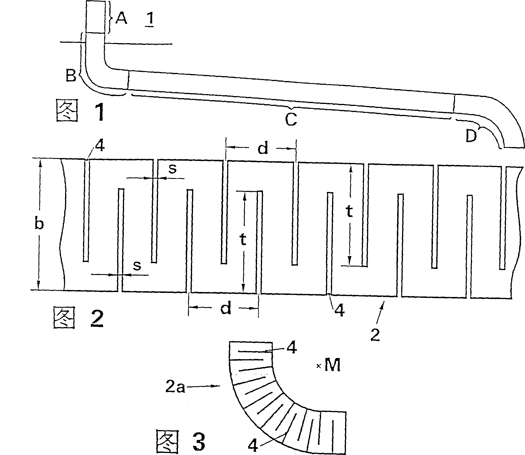
[0022] The stator winding bar of a large electric machine such as a turbo generator mainly consists of four parts: the slot or core part A, the more curved part B after the exit from the stator laminated core 1, and the less curved part about 150 cm or longer length portion C and a further more curved portion D adjoining portion C from which further connections of the semiconductor strips are made.

[0023] During the manufacture of the conductor winding bars it is important that the surface of the conductor winding bars be as flat as possible, which is especially important for motors with indirect cooled stator windings. In the case of this model, the heat generated by the conductor winding rods is dissipated via the radial and / or axial cooling channels of the stator laminated core 1, so that, in the slot part A, only the comparative The wide sides guarantee good heat transfer, while the narrow sides of the semiconductor strips squeeze optimally into the grooves. Furthermore...


PUM

PropertyMeasurementUnit
Widthaaaaaaaaaa

Abstract

The stator winding of an electrical machine comprises conductor elements which are spaced apart from one another, are electrically insulated from one another and are surrounded over their entire length by common main insulation. The cavities, which are caused by the arrangement on both bar narrow sides of the conductor elements and the main insulation, are filled with an electrically semiconductive compound which, for its part, is covered by an electrically semiconductive strip. In order to provide a smooth bar surface, the electrically semiconductive strip is composed of a fiber-reinforced plastic, which has incisions on alternate sides of the narrow sides of the conductor bar oriented transversely with respect to the bar's longitudinal direction; these incisions are deeper than half the strip width and have a cut width which is on the order of magnitude of the strip thickness.

Description

technical field [0001] The invention relates to a conductor winding bar for a stator winding of an electric motor, which consists of mutually transposed and mutually electrically insulated winding segments covered with a common main insulation over their entire length, the transposed winding segments being placed in a bundle of conductors A cavity is created on the narrow side between the winding wire section and the main insulation, the cavity is filled with a semiconducting substance, which is covered on one side with a semiconducting layer or strip. Background technique [0002] For the prior art related to the present invention, see US-PS 5066881, for example. [0003] The conductor winding bars of the stator windings of larger sizes consist of mutually transposed and mutually electrically insulated winding wire sections, covered over their entire length by a common main insulation, i.e. this main insulation covers both winding end sections or Bracket segment and core p...

Claims


Application Information

Patent Timeline
IPC IPC(8): H02K3/14H02K3/04H02K3/32H02K3/34H02K3/40
CPCH02K3/40H02K3/14
Inventor T·包曼J·厄斯特赫德
Owner ALSTOM (SWITZERLAND) LTD
Why Eureka
Try Eureka