Eureka AIR delivers breakthrough ideas for toughest innovation challenges, trusted by R&D personnel around the world.

System and method for eliminating local hot spots of server cabinet at data center

A technology for server cabinets and local hotspots, which is applied in the construction of electrical equipment components, cooling/ventilation/heating transformation, modification with gaseous coolant, etc. It can solve problems such as mixing of cold and hot air, return of hot air, and waste of cooling capacity. Achieve the effect of reducing local temperature, prolonging service life and ensuring stable operation

Active Publication Date: 2019-08-06
SOUTHEAST UNIV +1
View PDF8 Cites 7 Cited by
  • Summary
  • Abstract
  • Description
  • Claims
  • Application Information

AI Technical Summary

Problems solved by technology

[0004] 1. Insufficient air supply volume of the air conditioner causes cooling of some cabinets to fail to meet the requirements
[0005] 2. There is a gap at the bottom of the cabinet, causing hot air to flow back to the cabinet entrance
[0006] 3. There are gaps between adjacent cabinets, resulting in the mixing of hot and cold airflow and waste of cooling capacity
[0007] 4. The airtightness of the cabinet itself is not good. For example, if the empty cabinet position is not closed with a blind plate, the cold air flow will flow out without passing through the server.
However, this method will increase the power consumption of the air conditioner, especially reduce the air supply temperature of the air conditioner in the computer room. According to statistics, every time the supply air temperature decreases by one degree, the cooling capacity of the refrigeration unit will decrease by 3-4%, and the reduction in cooling capacity has to be increased. unit, resulting in a waste of electric energy, therefore, it is necessary to develop a device that can detect local hot spots in the cabinet and automatically eliminate them

Method used


Image

  • System and method for eliminating local hot spots of server cabinet at data center
  • System and method for eliminating local hot spots of server cabinet at data center
  • System and method for eliminating local hot spots of server cabinet at data center

Examples


Embodiment Construction

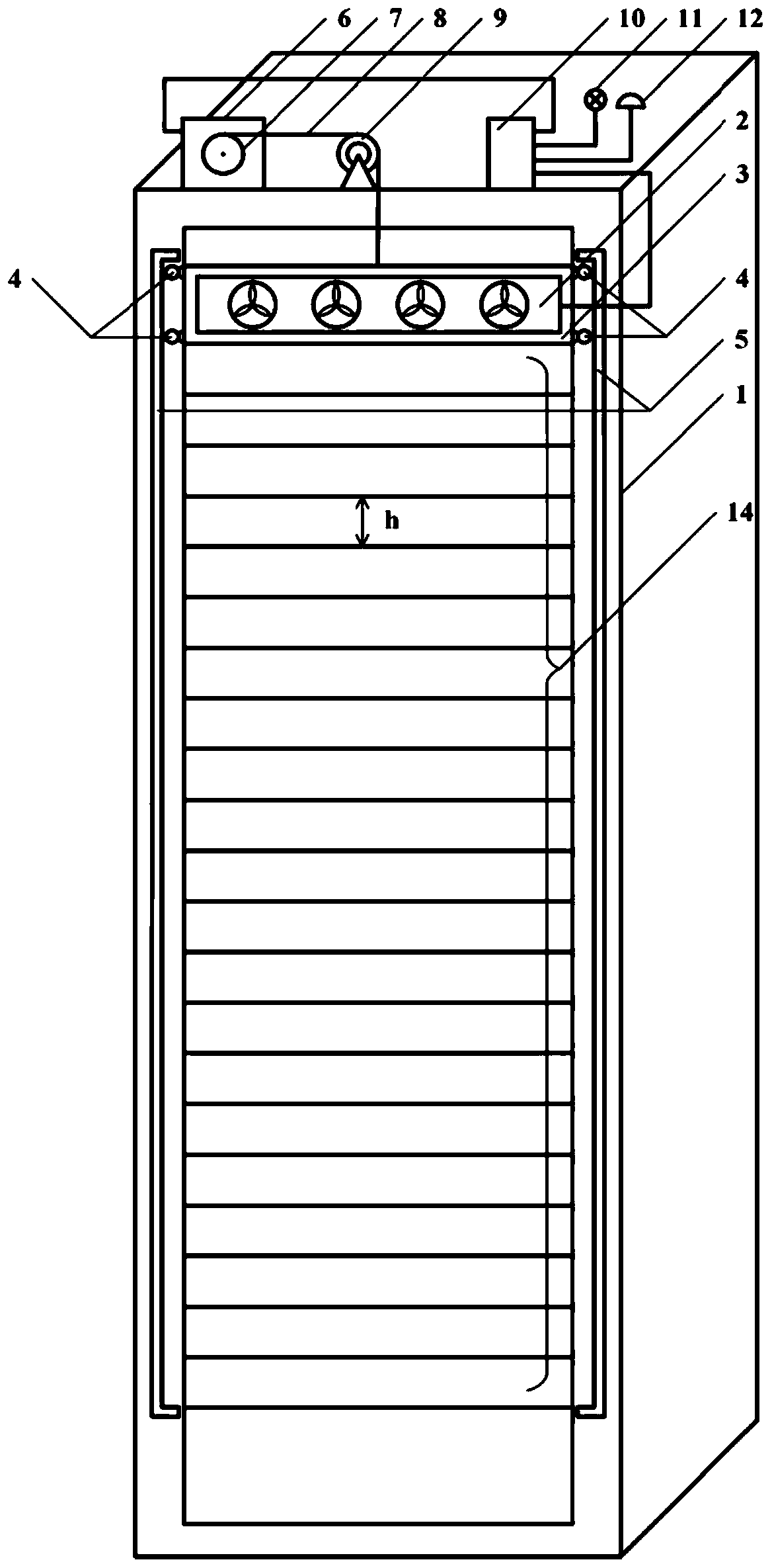
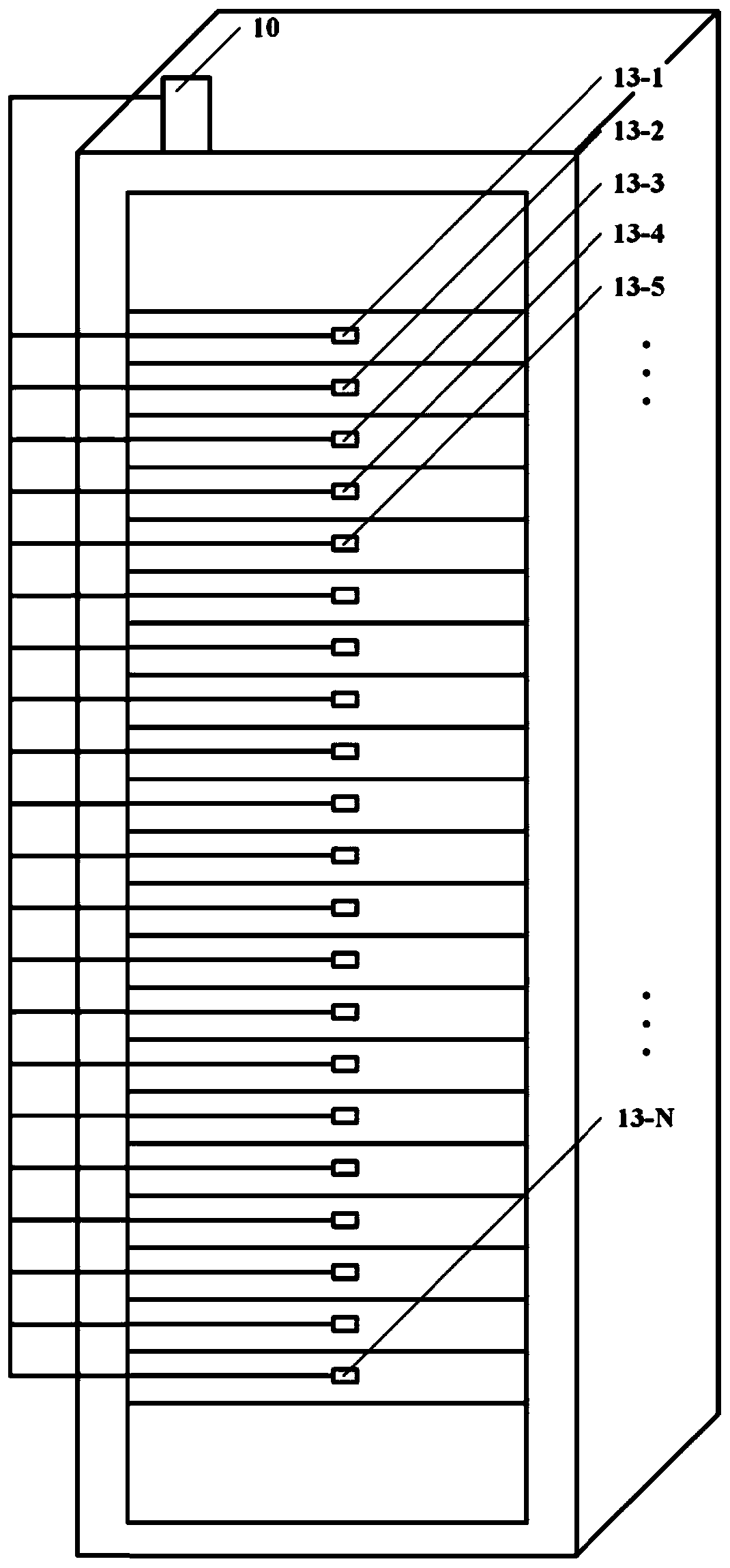
[0038] Such as figure 1 and figure 2 As shown, the local hot spot elimination system of the data center server cabinet of the present invention includes a server cabinet 1, a heat dissipation fan group 2, a fan bracket 3, a guide wheel 4, a guide rail 5, a stepping motor 6, a traction disc 7, a traction rope 8, a fixed Pulley 9, controller 10, alarm indicator light 11, buzzer 12, temperature sensor 13-i (i=1, 2, ..., N).

[0039]The server cabinet 1 may have various specifications. When the server cabinet 1 in this example is fully loaded, N servers can be placed therein. The guide rails 5 are fixed on both sides of the front of the cabinet. The four corners of the fan bracket 3 are equipped with guide wheels 4 embedded in the guide rails 5 on both sides so that they can slide vertically. The cooling fan group 2 is installed on the fan bracket 3.

[0040] The stepping motor 6 and the fixed pulley 9 are all fixed on the top of the cabinet 1, the power transmission shaft of t...


PUM


Abstract

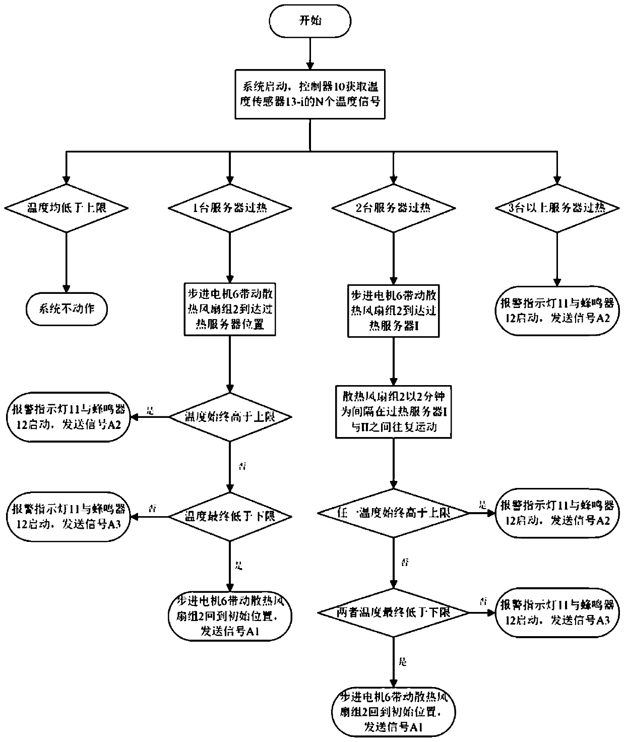
The invention discloses a system and method for eliminating local hot spots of a server cabinet at a data center. The system comprises a server cabinet, a cooling fan group, a fan bracket, a guide rail, a stepping motor, a traction rope, a fixed pulley, a controller and temperature sensors, wherein the stepping motor is connected with the cooling fan group through the traction rope and can drive the cooling fan group to move up and down along the guide rail; and the controller detects local hot spots of the cabinet through the temperature sensors, so that the stepping motor is driven to rotatefor a certain number of turns, the cooling fan group is enabled to reach the air inlet position of an overheated server to increase the air supply volume at the position, enhance heat dissipation andeliminate the local shot spots. The system can automatically carry out accurate air supply on the overheated server, thereby lowering the temperature, ensuring the stable operation of the server, andprolonging the service life. Meanwhile, the air conditioner temperature is avoided from being lowered, and the energy consumption of the data center is reduced.

Description

technical field [0001] The invention relates to a system and method for eliminating local hotspots in a server cabinet of a data center, and belongs to the field of cooling of the cabinets of a data center. Background technique [0002] In recent years, with the explosive growth of data processing business needs and the rapid progress of computer network technology, the scale and capacity of data centers have continued to expand. At present, my country's data center construction has entered a period of rapid development. The heat density of data centers is on the rise every year, and this trend is still continuing. For example, the heat density of new rack servers and blade servers used in large quantities has reached 20~30kW / rack. Rising heat densities make data centers more prone to rack overheating, which can lead to server thermal shutdowns. Server failure will not only cause economic losses, but also reduce its service life, and even cause irreversible data loss. The...

Claims


Application Information

Patent Timeline
Patent Type & Authority Applications(China)
IPC IPC(8): H05K7/20
CPCH05K7/20136H05K7/20172H05K7/20209
Inventor 马昕宇臧小虎王军杜垲
Owner SOUTHEAST UNIV
Why Eureka
Eureka Blog
Learn More