
A miniature vertical takeoff and landing flapping wing aircraft

A flapping-wing aircraft and vertical take-off and landing technology, applied in the field of flapping-wing aircraft, can solve problems such as increasing power consumption, reducing payload, and increasing take-off weight of the flapping-wing aircraft, achieving light structure, low power consumption, and increasing practical The effect of using performance

Active Publication Date: 2021-02-02
西北工业大学太仓长三角研究院 +1
View PDF4 Cites 0 Cited by
  • Summary
  • Abstract
  • Description
  • Claims
  • Application Information

AI Technical Summary

Problems solved by technology

[0003] Chinese Patent Publication No.: CN108557074A, publication date September 21, 2018, the title of the invention is a flapping-wing aircraft with a three-rotor hybrid layout and a control method. The application discloses a layout form combining a three-rotor and a flexible flapping wing. It aims to solve the problem that the existing flapping-wing aircraft cannot take into account both vertical take-off and landing and fast level flight. The aerodynamic coupling problem between the rotor and the flapping wing system is also difficult to solve
Chinese Patent Publication No.: CN108363408A, publication date January 26, 2018, the title of the invention is a flapping-wing aircraft autonomous take-off control system and method, the application discloses a method of using a remote control car to load the flapping-wing aircraft to take off. The most important thing is that the device can only be used once, and it is essentially the same as hand-throwing
When the flapping-wing aircraft lands directly on the ground during fixed-point investigation, it will greatly limit its detection field of vision. For example, the "homing pigeon" bionic detection flapping wing system developed by Northwestern Polytechnical University in China has a camera installed on the abdomen of the flapping wing. If it lands directly on the ground, the reconnaissance mission cannot be continued. In view of this problem, the team proposed a solution using bionic landing gear. The bionic landing gear system and landing control method, the imitation bird claw structure proposed by the invention can make the flapping wing aircraft perch on the wires and branches, and its deficiency is to add a set of corresponding drive system to increase the mechanical bird claw device. At the same time, the take-off weight of the flapping wing aircraft is increased, and its payload is reduced
For the fixed-point perch of the flapping wing aircraft, it involves the research field of perch and perch robots. In addition to the bionic landing gear structure mentioned above, there are also methods such as magnetic adsorption and vacuum adsorption. However, in combination with practical applications, these methods are all There are many deficiencies, so the bionic perch of the flapping wing aircraft is still a difficult problem to solve

Method used


Image

  • A miniature vertical takeoff and landing flapping wing aircraft
  • A miniature vertical takeoff and landing flapping wing aircraft
  • A miniature vertical takeoff and landing flapping wing aircraft

Examples


Embodiment Construction

[0028] The present invention will be further described in detail below in conjunction with the accompanying drawings and specific embodiments.

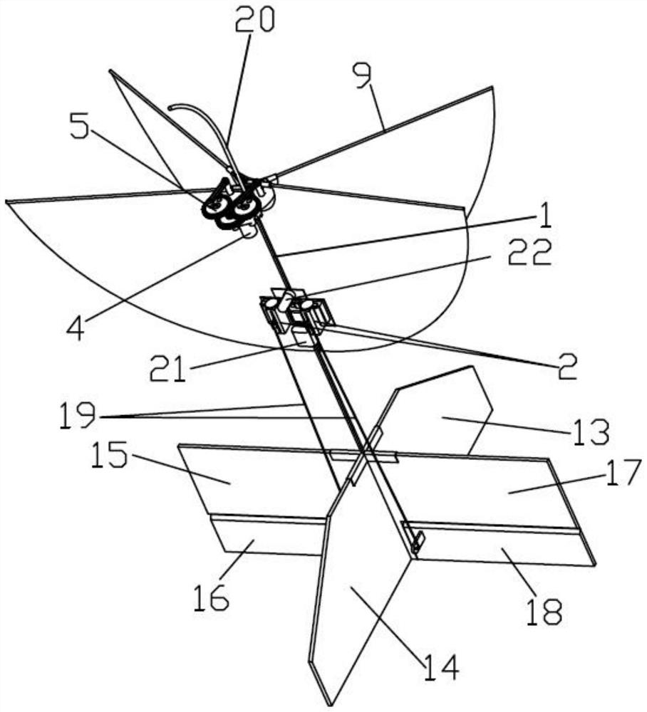
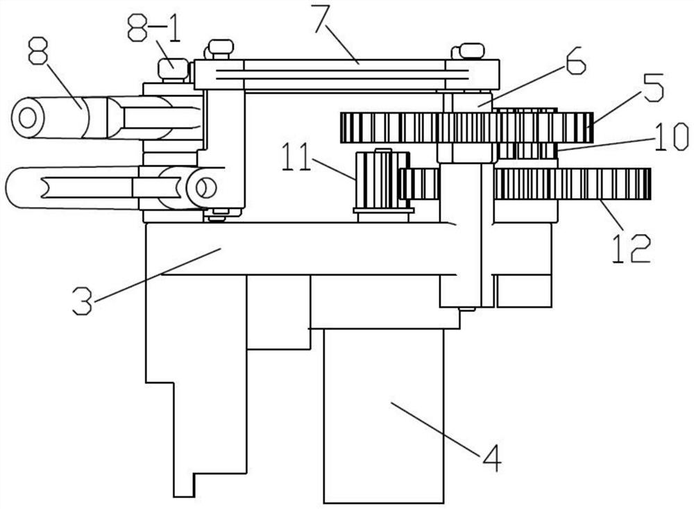
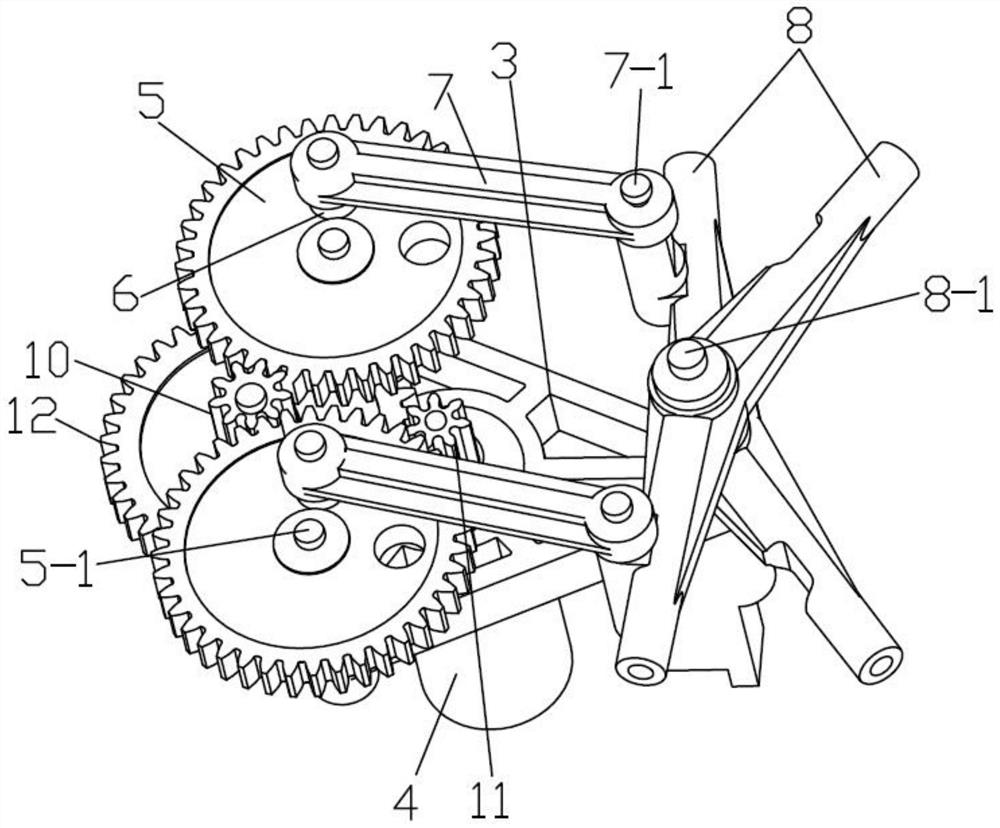
[0029] Depend on Figure 1~4 As can be seen from the illustrated embodiment, the present embodiment comprises a fuselage 1, a flight control system (from the prior art), a steering gear 2, a flapping device with two wings and a tail rudder, and the flapping device with two wings is arranged on the top of the fuselage 1 , the tail rudder is a cross-shaped support tail rudder, which is arranged on the lower part of the fuselage 1;

[0030] The double-wing flapping device includes a flapping-wing driving part and a flapping-wing synchronous motion mechanism installed on the frame 3;

[0031]The flapping wing drive part includes a motor 4 (model: GA12-N20; 614 strong magnetic hollow cup motor) and a reduction gear set. The motor 4 is meshed with the input end gear 12 of the reduction gear set through the motor shaft gear 11 arranged on i...


PUM


Abstract

The invention discloses a miniature vertical take-off and landing flapping-wing aircraft, and belongs to the technical field of flapping-wing aircrafts. The aircraft comprises an aircraft body, a flight control system, a steering engine, a double-wing flapping wing device and a tail vane. The double-wing flapping wing device is arranged at the upper part of the aircraft body, and the tail vane isarranged at the lower part of the aircraft body. The double-wing flapping wing device comprises a flapping wing driving part and a flapping wing synchronous movement mechanism which are mounted on a rack. The flapping wing driving part comprises a motor and a reduction gear set, the motor is in meshed connection with an input end gear of the reduction gear set through a motor shaft gear arranged on a rotating shaft of the motor, and the flapping wing synchronous movement mechanism comprises a flapping wing and a pair of flapping wing driving structures of the same structure. The flapping wingcomprises a flapping wing rocker arm and two pairs of flexible flapping wings. The flapping wing driving structure comprises an eccentric shaft mounting gear, an eccentric shaft and a connecting rod.The cross-shaped supporting tail vane comprises a longitudinal fixed rudder plate and a transverse adjusting rudder plate, and the longitudinal fixed rudder plate and the transverse adjusting rudder plate are vertically downward and are arranged in a cross mode. The aircraft has the characteristics of convenient take-off and landing, low energy consumption and the like.

Description

technical field [0001] The invention relates to the technical field of flapping-wing aircraft. Background technique [0002] The bionic flight of flapping-wing aircraft has broad application prospects in national defense and military affairs. When the flapping-wing aircraft is flying, the energy it carries is limited, which requires it to save energy as much as possible in the process of performing tasks. , it is required to hide in a certain corner for fixed-point monitoring, and then take off again to perform the next task after the monitoring is completed), so the aircraft is required to complete landing or take-off actions at any time and place to deal with random situations, and this action is It needs to be completed without human intervention or indirect intervention, so it is required that the flapping wing aircraft must have the ability to take off and land autonomously with a small amount of energy consumption. [0003] Chinese Patent Publication No.: CN108557074...

Claims


Application Information

Patent Timeline
Patent Type & Authority Patents(China)
IPC IPC(8): B64C33/02B64C29/00
CPCB64C29/00B64C33/02
Inventor 宣建林马东福周文辉刘丹杨文青李育斌宋笔锋宋晓伟
Owner 西北工业大学太仓长三角研究院
Learn More