
Gradient functional material 3D printing device and working method

A gradient functional material and 3D printing technology, applied in the field of 3D printing, can solve the problems of inability to achieve gradient printing of multi-component ceramic materials and cannot meet the requirements, and achieve the effects of high density, good surface quality and high dimensional accuracy

Inactive Publication Date: 2019-08-06
SHANDONG UNIV
View PDF9 Cites 5 Cited by
  • Summary
  • Abstract
  • Description
  • Claims
  • Application Information

AI Technical Summary

Problems solved by technology

In 2016, the French 3DCeram company launched ceramic SL-3D printing equipment, but only realized the printing preparation of single-phase ceramic parts such as alumina and zirconia.
However, the inventor found that the above equipment and patents can only provide a single raw material during printing, and cannot realize the gradient printing of multi-component ceramic materials, and cannot meet the market demand for ceramic gradient functional materials with complex shapes (ceramic / ceramic, ceramic / metal, etc.) urgent need of

Method used


Image

  • Gradient functional material 3D printing device and working method
  • Gradient functional material 3D printing device and working method
  • Gradient functional material 3D printing device and working method

Examples


Embodiment 2

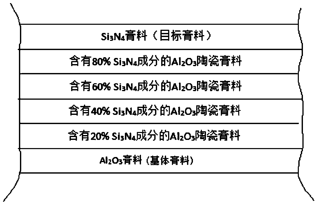
[0052] This embodiment discloses a working method of a gradient functional material 3D printing device: image 3 shown, including the following steps:

[0053] Step 1: Fill the base paste in the raw material bin, and fill the multi-component paste with different ratios into the barrel respectively, and each barrel is filled with a multi-component paste with a corresponding ratio.

[0054] In this embodiment, the base paste is made of Al 2 o 3 Paste, multi-component paste containing 20% ​​Si 3 N 4 Composition of Al 2 o 3 Ceramic paste, 40% Si 3 N 4 Composition of Al 2 o 3 Ceramic paste, 60% Si 3 N 4 Composition of Al 2 o 3 Ceramic paste, 80% Si 3 N 4 Composition of Al 2 o 3 Ceramic paste, the target paste is Si 3 N 4 For the paste, inject the four compatible multi-component pastes into the four barrels respectively, place the barrels on the barrel fixture, and use the upper computer to make marks in the controller.

[0055] Step 2: Input the information of t...

Embodiment 3

[0061] This embodiment discloses a working method of a gradient functional material 3D printing device, such as Figure 4 As shown, the base paste is made of ZrO 2 Paste, the target paste is stainless steel 316 paste, the multi-component paste is ZrO containing 10%, 20%, 30%, 40%, 50%, 60%, 70%, 80% stainless steel 316 2 The ceramic paste is filled in 8 barrels respectively. The part printing method is the same as that in Example 2, the difference is that the thickness of the first layer of the base paste layer is 30um, and the power of the laser is 210mW. The obtained gear structure has a smooth surface and basically no out of shape.


PUM


Abstract

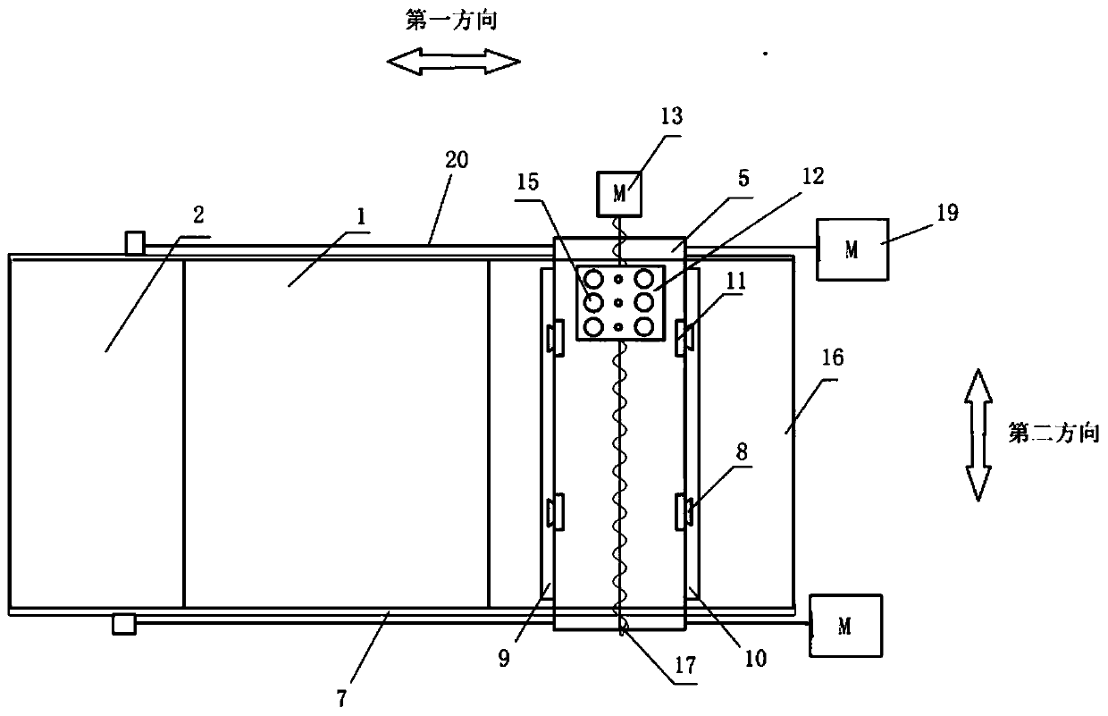
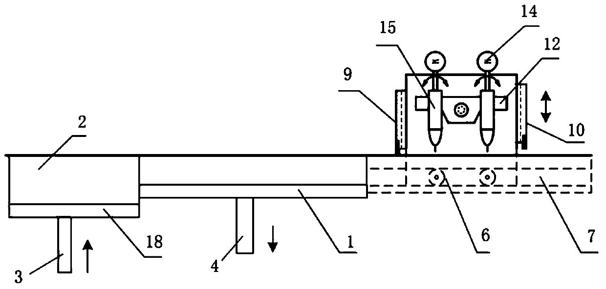
The invention relates to a gradient functional material 3D printing device and a working method. The gradient functional material 3D printing device comprises a raw material bin, a forming platform, atool reset, a plurality of charging barrels, and a laser curing mechanism, wherein a piston connected with a first lifting mechanism is arranged in the raw material bin; the forming platform is located one side of the raw material bin and connected with a second lifting mechanism; the tool rest is in sliding connection with first guide rails on two sides of the forming platform and connected witha second drive mechanism, the second drive mechanism can drive the tool rest to slide in the first direction, two end faces, perpendicular to the first direction, of the tool rest are in sliding connection with a scraper which is connected with a third lifting mechanism; the charging barrels are connected with a first drive mechanism fixed to the tool rest, the first drive mechanism is used for driving the charging barrels to move in the second direction perpendicular to the first direction, and the charging barrels are connected with a material extruding mechanism; and the laser curing mechanism is used for generating laser rays. The 3D printing device can realize 3D printing of functional gradient materials based on the SL technology.

Description

technical field [0001] The invention relates to the technical field of 3D printing, in particular to a gradient functional material 3D printing device and a working method. Background technique [0002] Functionally gradient materials (functionally gradient materials, FGM) are a new type of composite material composed of two or more materials with continuous gradient changes in composition and structure. It is a new type of functional material that can work normally and repeatedly in the environment. Studies have shown that functionally graded materials are different from homogeneous materials and composite materials from the perspective of material structure. It consists of two (or more) materials with different properties. By continuously changing the composition and structure of the two (or more) materials, the interface disappears, resulting in the performance of the material changing with the composition and structure of the material. Slowly changing to form a gradien...

Claims


Application Information

Patent Timeline
Patent Type & Authority Applications(China)
IPC IPC(8): B28B1/00B33Y30/00B33Y10/00
CPCB28B1/001B33Y10/00B33Y30/00
Inventor 邹斌邢宏宇王鑫锋刘晓艳
Owner SHANDONG UNIV
Learn More