Multi-functional network box protection device
What is Al technical title?
Al technical title is built by PatSnap Al team. It summarizes the technical point description of the patent document.
A protection device and network box technology, applied in the direction of clamping/drawing device, support structure installation, cooling/ventilation/heating transformation, etc., can solve the problem of single function
Active Publication Date: 2019-08-02
滨州高新区国有资本投资运营有限公司
View PDF8 Cites 5 Cited by
Summary
Abstract
Description
Claims
Application Information
AI Technical Summary
This helps you quickly interpret patents by identifying the three key elements:
Problems solved by technology
Method used
Benefits of technology
Problems solved by technology
[0002] The multi-function network box protection device can protect the multi-function network box, but the general multi-function network box protection device can only play a simple vibration isolation function, and the function is relatively single
Method used
Image
Click on the blue label to locate the original text in one second.
Reading with bidirectional positioning of images and text.
Examples
specific Embodiment approach 1
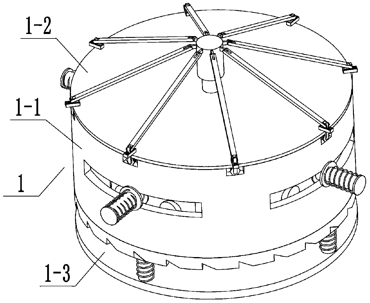
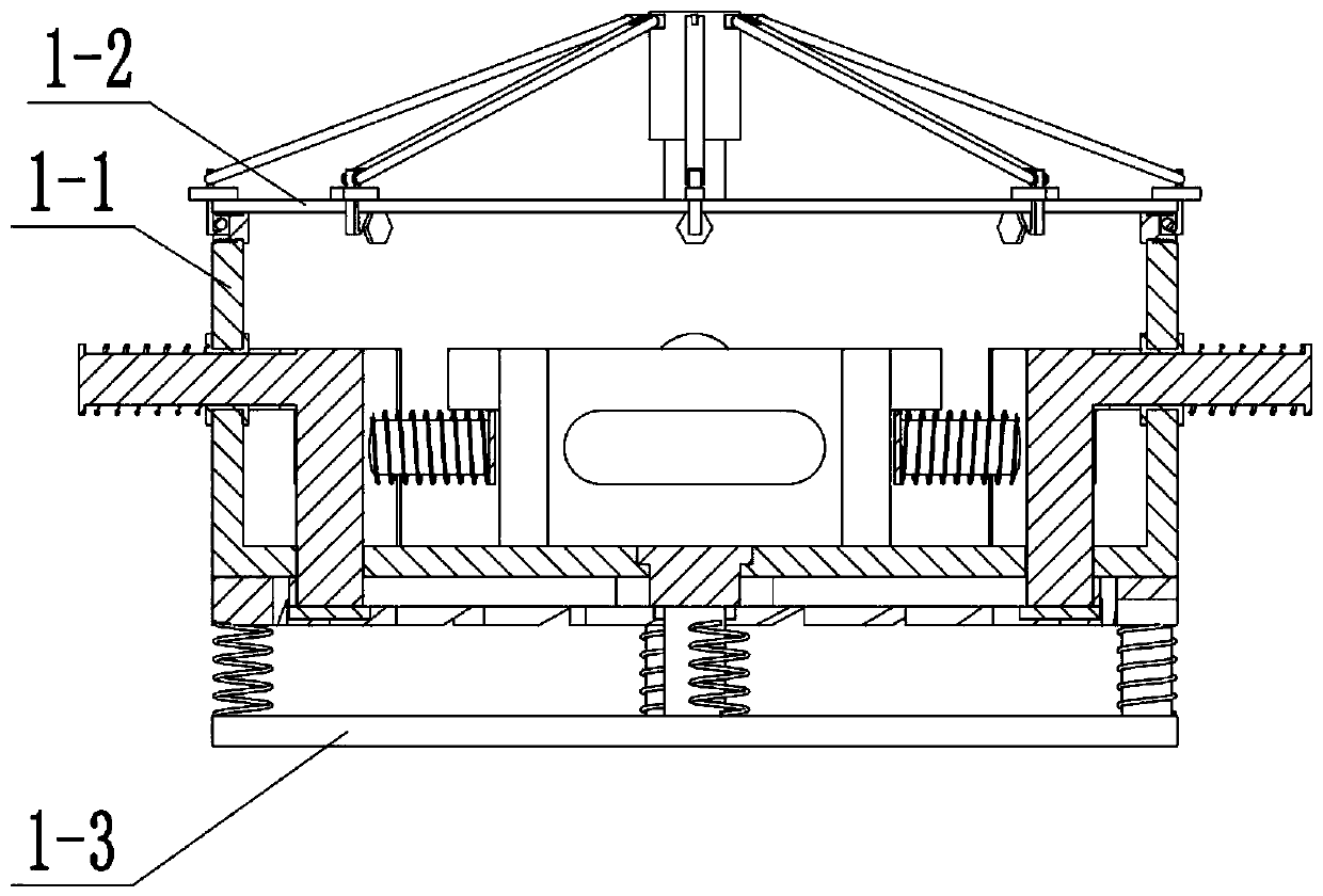
[0044] Combine below Figure 1-25 Describe this embodiment, a multifunctional network box protection device, including a fixed protection device 1, an external cooling device 2 and a lower buffer device 3, characterized in that: the fixed protection device 1 includes a protective outer frame 1-1, a sealing Cover 1-2, lower side rotating plate 1-3, protective outer frame body 1-4, inner end sliding slider assembly 1-5, lower side fixed clamping plate 1-6, side wall sliding waist groove 1-7, Lower side sliding waist groove 1-8, multiple side wall card slots 1-9, prismatic sliding hole 1-10, multiple lower side card slots 1-11, side wall card posts 1-12, side wall card post push Spring 1-13, inner clamping column 1-14, inner clamping column slot 1-15, inner sliding push plate 1-16, connecting sleeve 1-17, inner pusher push rod 1-18, inner pusher Sub-push spring 1-19, lower hinged sliding post 1-20, middle cylindrical sliding hole 1-21, rear hinged sliding post 1-22, rear sliding...
specific Embodiment approach 2
[0051] Combine below Figure 1-25 This embodiment will be described, and this embodiment will further describe the first embodiment, the inner lever push spring 1-28 and the middle end push spring 1-29 are both in a compressed state.
specific Embodiment approach 3
[0053] Combine below Figure 1-25 Describe this embodiment, this embodiment will further explain Embodiment 1, the speed regulation output shaft 2-13 is provided with a chute, the speed regulation output pulley 2-14 is provided with a sliding boss, the speed regulation output pulley The sliding boss provided on the 2-14 is connected in the chute provided on the speed-regulating output shaft 2-13 with clearance fit.
PUM
Abstract
The invention relates to a multi-functional network box, and more specifically relates to a multi-functional network box protection device. The multi-functional network box protection device can fix and seal the multi-functional network box through a fixation and protection device, can fix multi-functional network boxes with different specifications through the fixation and protection device, cancarry out cooling on the fixation and protection device through an external cooling device so as to cool the multi-functional network box in the fixation and protection device and prevent the multi-functional network box from overheating, and can isolate vibration for the multi-functional network box through a lower buffer device. The multi-functional network box protection device comprises the fixation and protection device, the external cooling device and the lower buffer device. An inner pusher pushing rod is reversely pushed under the action of an elastic force of an inner pusher pushing spring so as to enable the inner pusher pushing rod to be extruded with the multi-functional network box and complete the fixation of the multi-functional network box; and a lower hinged sliding columnslides along a lower sliding waist groove to adjust the distance between multiple inner-end sliding pusher assemblies, thereby enabling the inner pusher pushing rods on the inner-end sliding pusher assemblies to be changed in spatial position.
Description
technical field [0001] The invention relates to a multifunctional network box, in particular to a protection device for a multifunctional network box. Background technique [0002] The multi-function network box protection device can protect the multi-function network box, but the general multi-function network box protection device can only play a simple vibration isolation function, and the function is relatively single. Contents of the invention [0003] The purpose of the present invention is to provide a multifunctional network box protection device, which can fix and seal the multifunctional network box by fixing the protection device; can fix multifunctional network boxes of different specifications through the fixed protection device; The protection device cools down, and then cools down the multi-function network box in the fixed protection device to prevent the multi-function network box from overheating; the multi-function network box can be isolated from vibrat...
Claims
Application Information
Patent Timeline
Application Date:The date an application was filed.
Publication Date:The date a patent or application was officially published.
First Publication Date:The earliest publication date of a patent with the same application number.
Issue Date:Publication date of the patent grant document.
PCT Entry Date:The Entry date of PCT National Phase.
Estimated Expiry Date:The statutory expiry date of a patent right according to the Patent Law, and it is the longest term of protection that the patent right can achieve without the termination of the patent right due to other reasons(Term extension factor has been taken into account ).
Invalid Date:Actual expiry date is based on effective date or publication date of legal transaction data of invalid patent.