
Clock signal generation circuit, driving chip, display device and clock signal generation method

A clock signal and generation circuit technology, applied in the field of clock signal generation and clock signal generation circuit, can solve problems such as energy consumption, reduce energy consumption, improve image display quality, and prevent sudden changes in frame rate.

Inactive Publication Date: 2019-08-02
CHIPONE TECH BEIJINGCO LTD
View PDF14 Cites 7 Cited by
  • Summary
  • Abstract
  • Description
  • Claims
  • Application Information

AI Technical Summary

Problems solved by technology

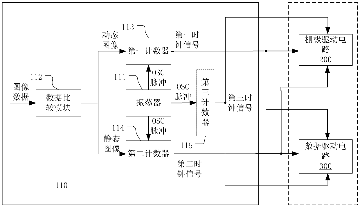
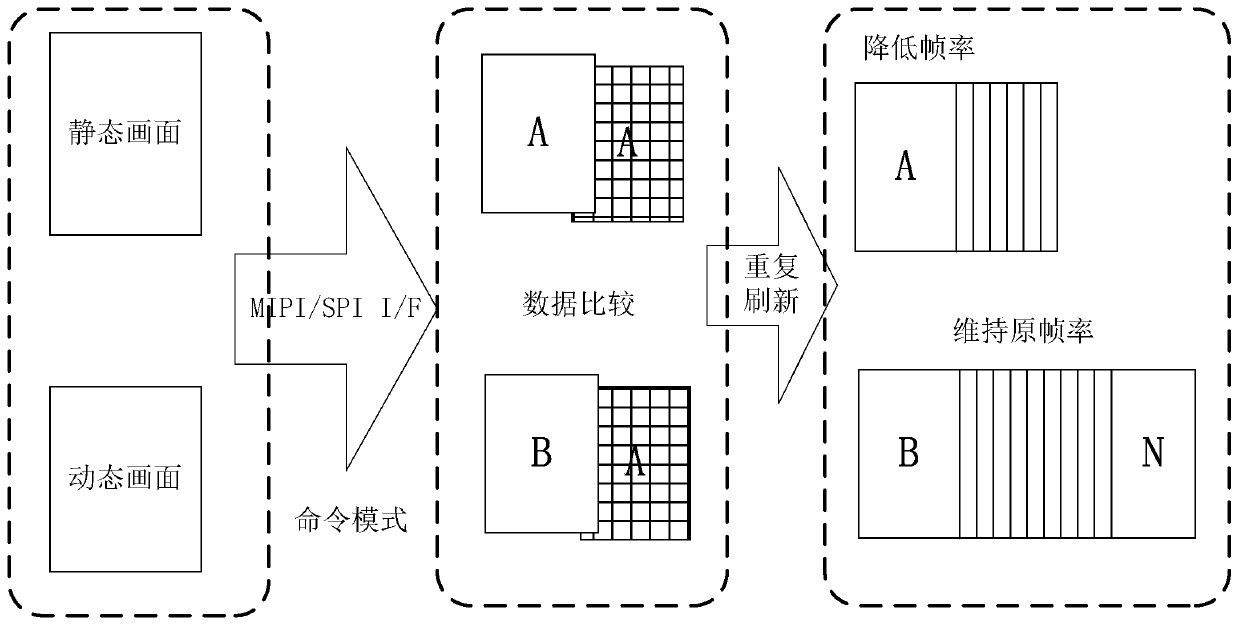
[0004] Therefore, when some electronic devices (such as mobile phones, computers or televisions) display images at present, the frame rate of the driver chip has a great relationship with the image quality. Generally speaking, the larger the frame rate, the clearer the displayed image. , but at the same time, increasing the frame rate means consuming more energy, especially in some unnecessary situations, such as displaying the same image for a certain period of time

Method used


Image

  • Clock signal generation circuit, driving chip, display device and clock signal generation method
  • Clock signal generation circuit, driving chip, display device and clock signal generation method
  • Clock signal generation circuit, driving chip, display device and clock signal generation method

Examples


Embodiment Construction

[0032] In order to facilitate the understanding of the present invention, the present invention will be described more fully below with reference to the associated drawings. Preferred embodiments of the invention are shown in the accompanying drawings. However, the present invention can be implemented in different forms and is not limited to the embodiments described herein. On the contrary, these embodiments are provided to make the understanding of the disclosure of the present invention more thorough and comprehensive.

[0033] Unless otherwise defined, all technical and scientific terms used herein have the same meaning as commonly understood by one of ordinary skill in the technical field of the invention. The terms used herein in the description of the present invention are for the purpose of describing specific embodiments only, and are not intended to limit the present invention.

[0034] Hereinafter, the present invention will be described in detail with reference t...


PUM


Abstract

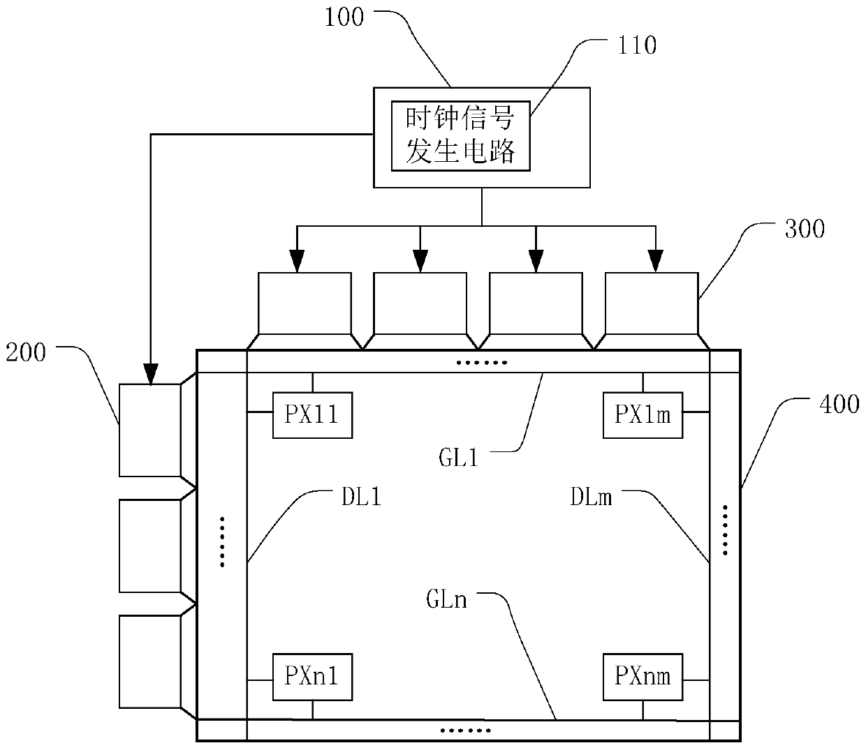
The invention discloses a clock signal generation method, which comprises the following steps of performing content comparison on the image data of the continuous frames, and judging whether the imagedata is a static image or a dynamic image; when the image data is the dynamic image, generating a first clock signal; when the image data is the static image, generating a second clock signal, and controlling the refresh frequency of the image display according to the first clock signal or the second clock signal, wherein the frequency of the first clock signal is higher than that of the second clock signal. The invention also discloses a clock signal generation circuit, a driving chip and a display device. According to the clock signal generation circuit, the display device and the clock signal generation method disclosed by the invention, the number of the image frames which can be refreshed by a driving chip per second is reduced, the frame rate is reduced, and the unnecessary energy loss is reduced.

Description

technical field [0001] The invention relates to the technical field of image display, in particular to a clock signal generation circuit, a drive chip, a display device and a clock signal generation method. Background technique [0002] Frame rate (Frame rate, referred to as: FR) is a measure used to measure the number of display frames, and the measurement unit is the number of display frames per second (Frames per Second, referred to as: FPS) or "Hertz (Hz)". Frames per second (FPS) or frequency can be used to express the number of times a graphics processor can update a field per second. Higher frequencies result in smoother, more realistic animations. Generally speaking, a frame rate of around 30Hz is acceptable to users, but if the performance is increased to 60Hz, the sense of interaction and realism can be significantly improved. [0003] The frame rate of the driver chip is mainly realized by the clock frequency of the chip OSC (Oscillator, oscillator) and the firs...

Claims


Application Information

Patent Timeline
Patent Type & Authority Applications(China)
IPC IPC(8): G09G3/20
CPCG09G3/20G09G2330/021
Inventor 宫仁敏
Owner CHIPONE TECH BEIJINGCO LTD
Learn More