
Voltage sag monitoring point optimal configuration method based on minimum amplitude search

A technology of voltage sag and optimized configuration, which is applied in the direction of measuring devices, measuring electricity, fault locations, etc., can solve the problems of monitoring blind areas and low calculation efficiency, achieve effective monitoring, eliminate monitoring blind areas, and improve engineering applicability

Active Publication Date: 2019-08-02
GUANGDONG POWER GRID CO LTD +1
View PDF6 Cites 14 Cited by
  • Summary
  • Abstract
  • Description
  • Claims
  • Application Information

AI Technical Summary

Problems solved by technology

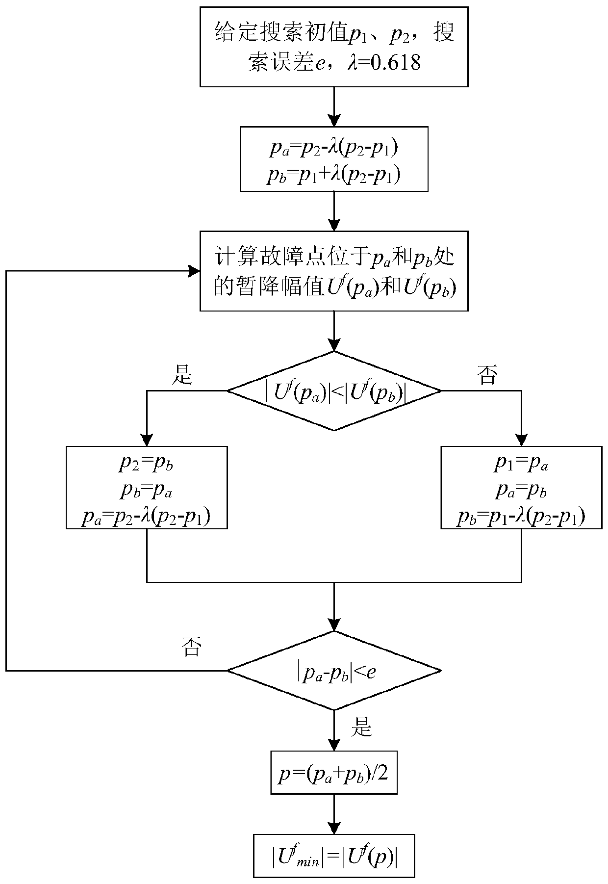
[0004] The present invention provides a method for optimal configuration of voltage sag monitoring points based on minimum amplitude search, searches for the minimum voltage sag amplitude of each node through the golden section method, optimizes configuration of sag monitoring points, and eliminates the existing voltage sag The optimal configuration method of drop monitoring points has the problems of monitoring blind areas and low calculation efficiency, and realizes effective monitoring of voltage sags in the entire network

Method used


Image

  • Voltage sag monitoring point optimal configuration method based on minimum amplitude search
  • Voltage sag monitoring point optimal configuration method based on minimum amplitude search
  • Voltage sag monitoring point optimal configuration method based on minimum amplitude search

Examples


Embodiment 1

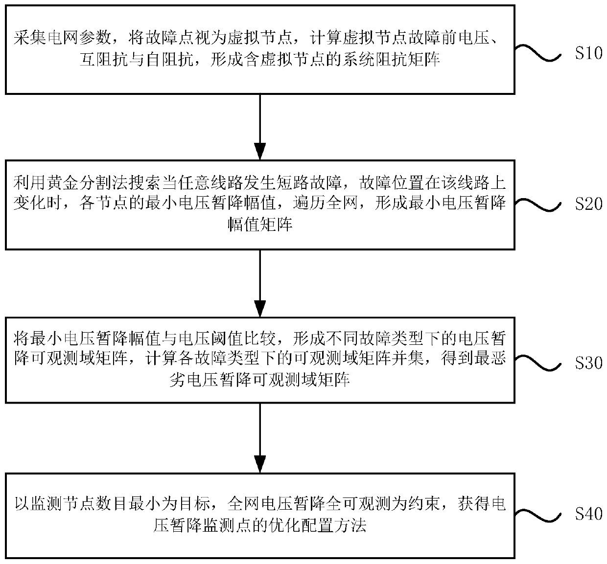
[0054] Please refer to the attached figure 1 , which is a schematic flowchart of a method for optimal configuration of voltage sag monitoring points based on minimum amplitude search provided in Embodiment 1 of the present invention. The method specifically includes the following steps:

[0055] S10. Collect power grid parameters, regard the fault point as a virtual node, calculate the voltage, mutual impedance and self-impedance of the virtual node before the fault, and form a system impedance matrix including the virtual node;

[0056] S20. Use the golden section method to search for the minimum voltage sag amplitude of each node when a short-circuit fault occurs on any line and the fault location changes on the line, and traverse the entire network to form a minimum voltage sag amplitude matrix;

[0057] S30. Comparing the minimum voltage sag amplitude with the voltage threshold, forming a voltage sag observable domain matrix under different fault types, calculating the uni...


PUM


Abstract

The invention discloses a voltage sag monitoring point optimal configuration method based on minimum amplitude search. The method comprises the following steps: collecting power grid parameters, regarding a fault point as a virtual node, and calculating voltage, mutual impedance and self-impedance before the fault of the virtual node, to form a system impedance matrix containing the virtual node;searching the minimum voltage sag amplitude of each node when any line has a short-circuit fault and the fault position changes on the line by using a golden section method, and traversing the whole network, to form a minimum voltage sag amplitude matrix; comparing the minimum voltage sag amplitude with a voltage threshold, to form voltage sag observable domain matrixes under different fault types, and calculating an observable domain matrix union under each fault type, to obtain a worst voltage sag observable domain matrix; and obtaining the optimal configuration method of the voltage sag monitoring point by taking the minimum number of the monitoring nodes as a target and taking the full observability of the whole network voltage sag as a constraint. The voltage sag monitoring blind areais eliminated, and the calculation efficiency is improved.

Description

technical field [0001] Embodiments of the present invention relate to the technical field of power quality monitoring and analysis, in particular to a method for optimal configuration of voltage sag monitoring points based on minimum amplitude search. Background technique [0002] Voltage sag is one of the most concerned problems in power quality. The International Institute of Electrical and Electronics Engineers (IEEE) defines it as the rapid drop of the root mean square value of the supply voltage to 90% to 10% of the rated value for a duration of 0.5 Power quality events with cycles up to 30 cycles. With the large investment of sensitive equipment in the power system, the economic loss of production caused by voltage sag is becoming more and more serious. If a fully observable monitoring system for voltage sags in the entire network can be established, the occurrence of voltage sags in the system can be effectively monitored in real time, and preventive measures can be ...

Claims


Application Information

Patent Timeline
IPC IPC(8): G01R31/08
CPCG01R31/088
Inventor 谢培成谢伟伦薛峰万四维许家凤陈欣晖黄志威陈蔚茹
Owner GUANGDONG POWER GRID CO LTD
Learn More