
Multi-channel small-diameter digital real-time imaging detection device

A real-time imaging and detection device technology, which is applied in the fields of nuclear reactor monitoring, reactors, nuclear power generation, etc., can solve the problems of inability to guarantee the rotation accuracy, affecting the rhythm requirements, and low work efficiency, so as to improve the detection production efficiency, widen the detection range, reduce the The effect of small protection against hazards

Pending Publication Date: 2019-07-30
DANDONG HUARI SCIENCE ELECTRIC CO LTD
View PDF0 Cites 0 Cited by
  • Summary
  • Abstract
  • Description
  • Claims
  • Application Information

AI Technical Summary

Problems solved by technology

[0002] At present, the non-destructive testing of fuel rods still stays in manual detection, and the end plugs of fuel rods are detected by filming. Although filming is simple, the disadvantages of low work efficiency, complexity, and serious pollution have always been problems in the testing industry.
With the continuous advancement of Industry 4.0, the X-ray non-destructive testing industry has higher and higher requirements for detection efficiency. The previous detection technology can no longer meet the current detection requirements for fuel rods.
Especially for the overall production process of fuel rods, automatic unmanned operation is adopted throughout the whole process. Traditional manual inspection affects the rhythm requirements of each process link and delays production. Moreover, the efficiency of manual rotation of fuel rods is low, and the rotation accuracy cannot be guaranteed. The production efficiency is extremely high. Low, traditional technology produces a series of defects and disadvantages, fuel rod manufacturers and users are in urgent need of a new fully automatic high-precision synchronous rotation detection device

Method used


Image

  • Multi-channel small-diameter digital real-time imaging detection device
  • Multi-channel small-diameter digital real-time imaging detection device
  • Multi-channel small-diameter digital real-time imaging detection device

Examples


Embodiment Construction

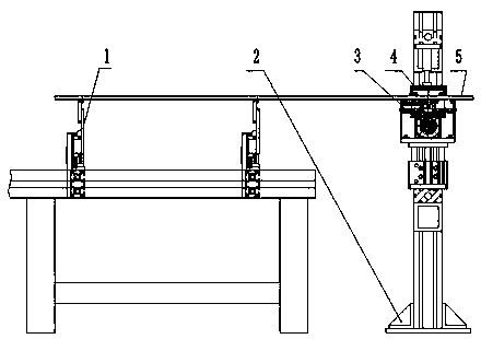
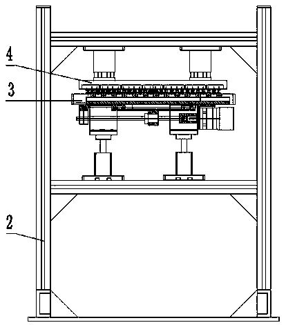
[0026] Such as Figure 1-Figure 10 The multi-channel small-diameter digital real-time imaging detection device shown includes a driven jacking roller 1, a fixed frame 2, a driving roller set 3, and a driven pressure roller set 4, wherein the driven jacking roller 1 is installed on the conveying line , arranged equidistantly with the driving roller group 3, the driving roller group 3 is installed on the jacking cylinder 205 of the fixed frame 2, and the driven pressure roller group 4 is installed on the pressing piece cylinder 206 of the fixed frame 2. The small-diameter rod (pipe) part 5 is located on the driving roller group 3, and the driven roller group 4 is below.

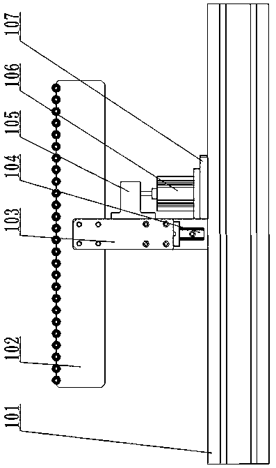
[0027] Driven jacking roller 1 comprises: fixed profile 101, driven wheel fixed seat plate 102, slide block fixed plate 103, linear guide rail 104, cylinder connecting plate 105, jacking cylinder 106, cylinder fixed plate 107, driven wheel shaft one 108, Spacer 109, driven wheel one 110, snap spring one 111; f...


PUM


Abstract

The invention discloses a multi-channel small-diameter digital real-time imaging detection device, which comprises: a driven jacking roller, a fixed frame, a jacking cylinder, a driving roller wheel group, a driven dynamic pressure wheel group and a pressing part cylinder, wherein the driven jacking roller is arranged on a conveying line and is arranged at equal intervals with the driving roller wheel group; the jacking cylinder is arranged on the fixed frame; the driving roller wheel group is arranged on the jacking cylinder; the pressing part cylinder is arranged on the fixed frame; the driven dynamic pressure wheel group is arranged on the pressing part cylinder. A plurality of small-diameter rod (pipe) pieces are supported and driven to rotate by means of the driving roller wheel group, and downward pressure is provided from the driven dynamic pressure wheel group to increase frictional force generated during rotation. The device fundamentally solves various defects of the traditional manual rotation of the small-diameter rod (pipe) pieces, improves the detection precision and the detection efficiency due to the adoption of high-precision automatic remote control, widens the application range, reduces the labor intensity of field workers, and is suitable for wide popularization.

Description

technical field [0001] The invention relates to a synchronous rotating mechanism for small-diameter rods (tubes), in particular to a multi-channel small-diameter digital real-time imaging detection device. Background technique [0002] At present, the non-destructive testing of fuel rods still stays in manual detection, and the end plugs of fuel rods are detected by filming. Although filming is simple, the disadvantages of low work efficiency, complexity, and serious pollution have always been problems in the testing industry. . As the process of Industry 4.0 continues to advance, the X-ray non-destructive testing industry has higher and higher requirements for detection efficiency. The previous detection technology can no longer meet the current detection requirements for fuel rods. Especially for the overall production process of fuel rods, automatic unmanned operation is adopted throughout the whole process. Traditional manual inspection affects the rhythm requirements o...

Claims


Application Information

Patent Timeline
Patent Type & Authority Applications(China)
IPC IPC(8): G21C17/06
CPCG21C17/06Y02E30/30
Inventor 谭晓超王成党彬孙典奎刘广大刘方秋宋俐许宪龙张焱鑫
Owner DANDONG HUARI SCIENCE ELECTRIC CO LTD
Learn More