
Receiver device of laser radar, and laser radar

A laser radar and receiver technology, applied in measurement devices, electromagnetic wave re-radiation, and utilization of re-radiation, etc., can solve the problems of complex design, low reliability and high cost of chip laser radar receivers, and achieve high reliability. , high sensitivity, low cost effect

Inactive Publication Date: 2019-07-30
VISIONICS MICROELECTRONICS TECH CO LTD
View PDF8 Cites 3 Cited by
  • Summary
  • Abstract
  • Description
  • Claims
  • Application Information

AI Technical Summary

Problems solved by technology

The multi-chip lidar receiver solution is complex in design, high in cost, bulky, and low in reliability

Method used


Image

  • Receiver device of laser radar, and laser radar
  • Receiver device of laser radar, and laser radar
  • Receiver device of laser radar, and laser radar

Examples


Embodiment Construction

[0021] The present invention will be described in detail in some embodiments as follows. However, other than the disclosed embodiments, the scope of the present invention is not limited by these embodiments, but only by the following claims. In order to provide a clearer description and enable ordinary people in the art to understand the content of the invention, the various parts in the illustrations are not drawn according to their relative sizes, and the proportions of certain dimensions or other relative dimensions may be highlighted It appears exaggerated, and irrelevant details are not fully drawn in order to simplify the diagram.

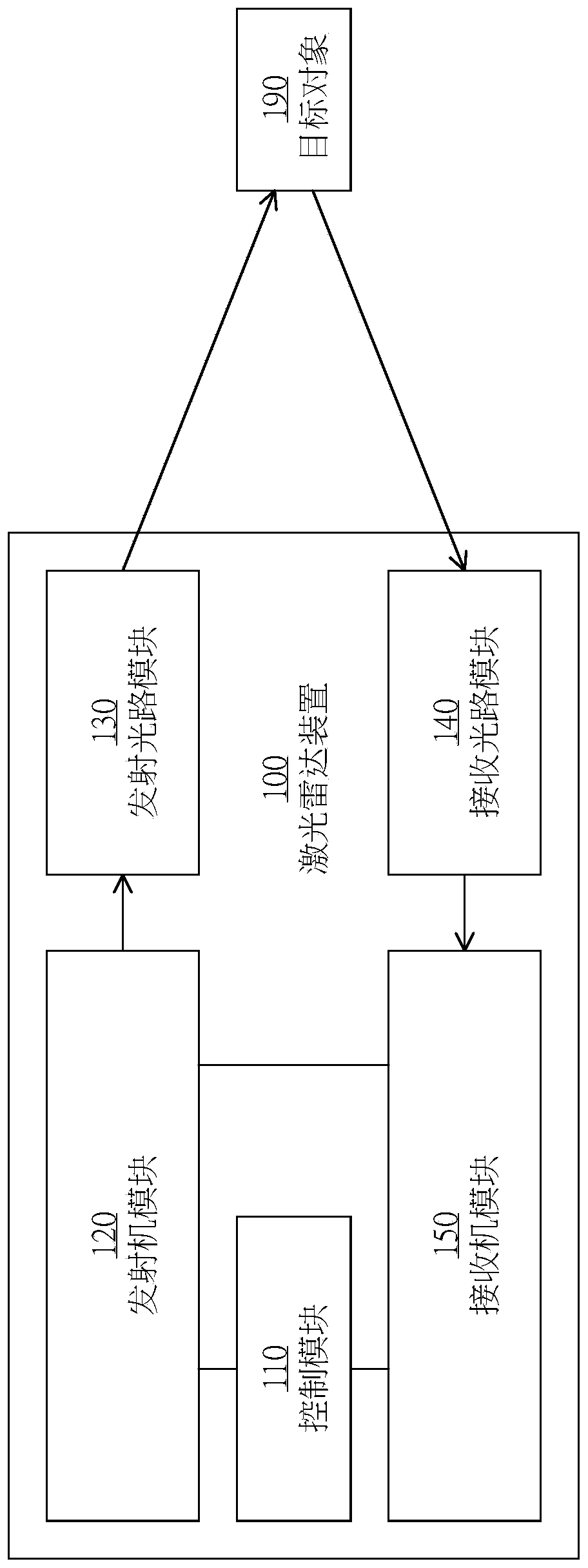
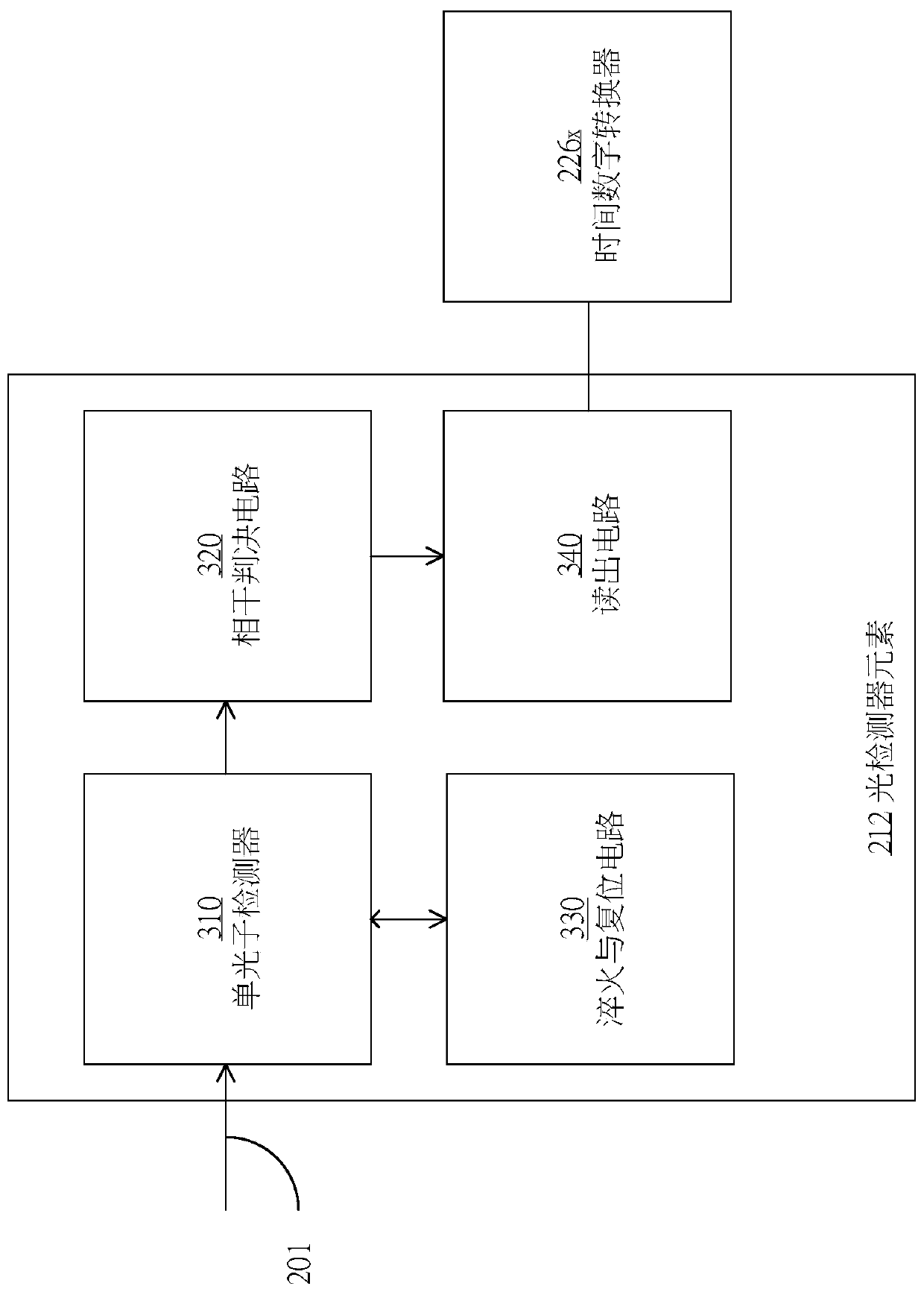
[0022] Please refer to figure 1 As shown, it is a schematic block diagram of a lidar 100 according to an embodiment of the present invention. The laser radar 100 includes the following modules: a control module 110 for controlling the entire laser radar 100, a transmitter module 120 for generating laser light, an emission optical path modul...


PUM


Abstract

The invention provides a receiver device of a laser radar, and the laser radar. The technical field of the invention is the laser radar, and in particular is the receiver device about the laser radar.The receiver device of the laser radar comprises an optical detector array module, a clock signal module and a receiver control module; the clock signal module is connected to the optical detector array module, and comprises multiple time-to-digital converters; the receiver control module is connected to the clock signal module, wherein the receiver device is arranged in a single encapsulation body. The technical points of the receiver device of the laser radar, and the laser radar in the invention are as follows: the receiver device is arranged in the single encapsulation body; the development difficulty and the system cost of the receiver system of the laser radar are reduced; the integration of the system is provided; and thus, miniaturization of the system is realized.

Description

technical field [0001] The present invention relates to LIDAR, and in particular to a receiver device for LIDAR. Background technique [0002] LiDAR is a non-contact active optical ranging system, which can stably and reliably measure the distance, size and intensity of target objects in space. In the fields of unmanned automobiles and 3D vision of robots, lidar can provide high-resolution point cloud data and 3D scene reconstruction functions, and will not be affected by external factors, such as day and night, temperature, environment, and weather. [0003] Traditional lidar system design, especially the receiver needs to use a variety of chips. These chips cooperate in a receiver system to realize the three-dimensional distance measurement function of the object. The multi-chip lidar receiver solution is complex in design, high in cost, bulky, and low in reliability. [0004] Therefore, designing a laser radar receiver system chip with a high degree of integration tha...

Claims


Application Information

Patent Timeline
Patent Type & Authority Applications(China)
IPC IPC(8): G01S7/491G01S7/4865G01S7/4863G01S17/10G01S17/89
CPCG01S7/4912G01S7/4816G01S7/4863G01S17/10G01S7/4865G01S17/89
Inventor 俞坤治李成黄晓林
Owner VISIONICS MICROELECTRONICS TECH CO LTD
Learn More