Magnetic valve and vehicle cooling system utilizing magnetic valve

A cooling system, magnetic technology, applied in the layout of the cooling combination of the power unit, vehicle components, valve operation/release devices, etc., can solve the problems of lip seal leakage, increased integration difficulty, and mechanical parts stuck. , to achieve easy integration, reduce leakage risk, and reduce HC&CO emissions

Pending Publication Date: 2019-07-30
SHANGHAI BLOOMLINK ELECTRONICS TECH CO LTD
View PDF0 Cites 0 Cited by
  • Summary
  • Abstract
  • Description
  • Claims
  • Application Information

AI Technical Summary

Problems solved by technology

[0003] Since the ball valve is driven by a motor, the sealing performance must also be considered when the valve rotates, resulting in a complex structure and high cost; failure of the motor or stuck mechanical parts will cause the cooling water channel of the automobile water tank to be blocked or the flow resistance is too large to cause engine cooling water temperature Too high, there is a risk of pulling the cylinder or increasing fuel consumption; the drive shaft of the valve body is in a rotating state when it is working, and there is a risk of leakage of the lip seal after a certain period of time; the volume is large, and the difficulty of integration increases

Method used


Image

  • Magnetic valve and vehicle cooling system utilizing magnetic valve
  • Magnetic valve and vehicle cooling system utilizing magnetic valve

Examples


Embodiment Construction

[0022] Embodiments of the present invention will be further described below in conjunction with the accompanying drawings.

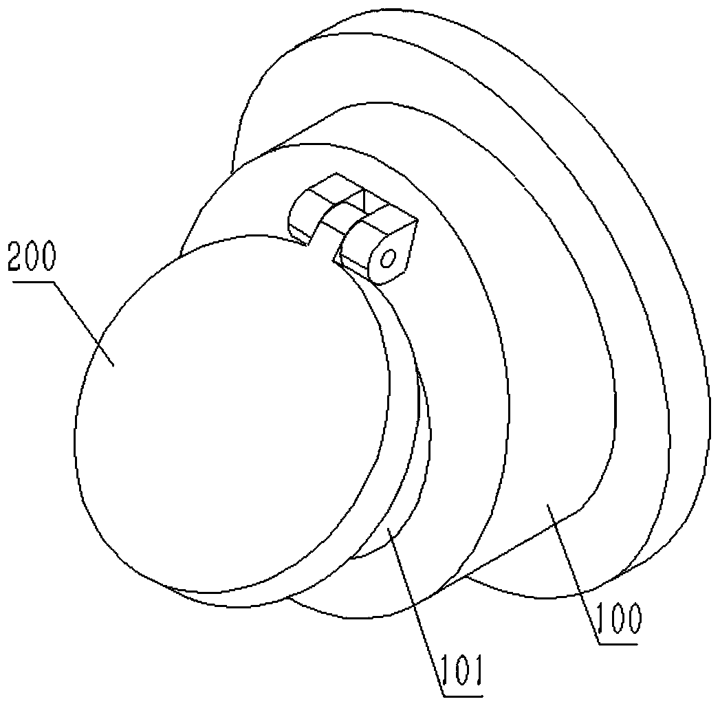
[0023] Please see attached figure 1 As shown, a magnetic valve includes a valve body 100 and a valve cover 200; the middle part of the valve body 100 is provided with a through passage 101, the valve cover 200 and the valve body 100 are hinged, and when the two are in contact, the valve The cover 200 closes the through passage 101; the contact between the valve body 100 and the valve cover 200 is polished to form a sealing surface.

[0024] The valve body 100 is made of temperature-sensitive ferrite iron, and the valve cover 200 is made of permanent magnet.

[0025] The valve body 100 is made of permanent magnets, and the valve cover 200 is made of temperature-sensitive ferrite iron.

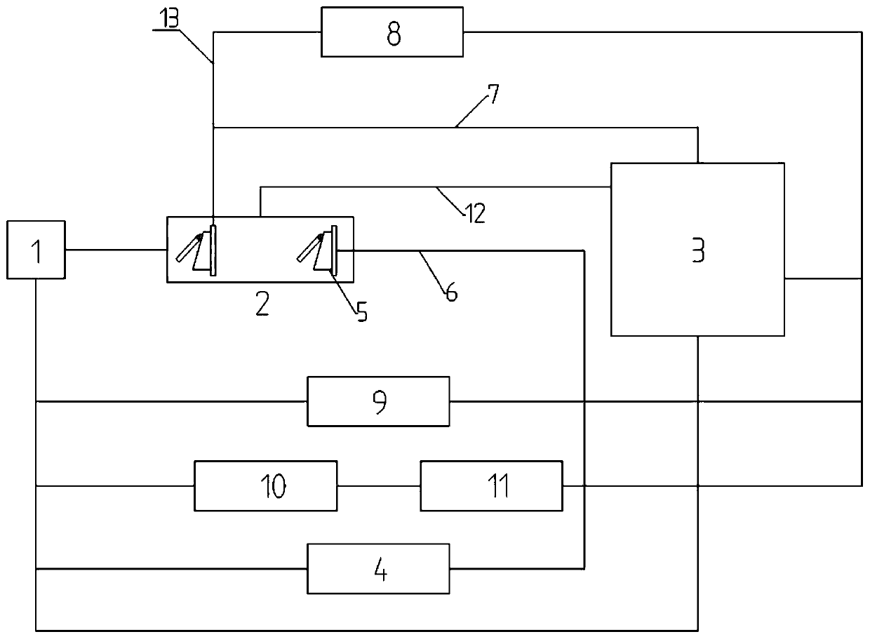
[0026] Please see attached figure 2 As shown, the present invention also discloses a vehicle cooling system using the magnetic valve, including an electronic water pum...


PUM


Abstract

The invention discloses a magnetic valve, and further discloses a vehicle cooling system utilizing the magnetic valve. The magnetic valve comprises a valve body and a valve cover. The vehicle coolingsystem comprises an electronic water pump, a TMM, an engine, a water tank and the magnetic valve. According to the magnetic valve and the vehicle cooling system, the magnetic valve and the electronicwater pump act together, and fuel economy can be improved in working condition actual measurement of national fuel consumption tests; the magnetic valve is arranged in a TMM module and only has staticseal compared with other valves having dynamic seal, the leaking risk of a cooling liquid is greatly reduced, and the risks of cylinder scoring and fuel consumption increase due to leakage of the cooling liquid after sale are eliminated; compared with conventional ball valves, the magnetic valve has the advantage that cost is greatly reduced, volume of a product is smaller, and the magnetic valveis easier to integrate in an integrated vehicle; and magnetic force is matched with output pressure of the water pump, the valve can be opened in a forced manner under pressure even temperature doesnot reach the curie point at a certain pressure point, and the problem that a motor loses efficacy during the utilization process of the ball valves is eliminated.

Description

technical field [0001] The invention relates to the technical field of automobile thermal management, in particular to a magnetic valve and a vehicle cooling system using the magnetic valve. Background technique [0002] At present, the ball valve in the automotive thermal management system module (TMM) is driven by a motor, and the opening of the ball valve is determined by the temperature to realize the conduction of different water outlets and the flow of cooling water after conduction. The water in the cylinder block and cylinder head participates in the flow, and the cooling water of the air conditioner heater (HVAC Heater), the cooling water of the radiator (Radiator), the cooling water of the transmission oil (TOC) and the cooling water of the exhaust gas recirculation valve body (EGR) etc. The cooling water is isolated, so that the temperature of the cooling water of the engine is rapidly increased, so as to reduce cylinder friction, reduce idle speed, reduce fuel in...

Claims


Application Information

Patent Timeline
Patent Type & Authority Applications(China)
IPC IPC(8): F16K1/20B60K11/02F16K31/66F16K27/02
CPCB60K11/02F16K1/20F16K27/0209F16K31/002F16K31/0644
Inventor 傅忠华
Owner SHANGHAI BLOOMLINK ELECTRONICS TECH CO LTD
Why Eureka
Try Eureka