
Dynamic testing platform for leg joints of foot-type bionic robot

A bionic robot and dynamic testing technology, which is applied in the direction of machine gear/transmission mechanism testing, etc., can solve the problems of lack of overall joint application effect testing, complicated process, high cost, etc., and achieve simple structure, time and cost saving, and convenient operation Effect

Pending Publication Date: 2019-07-26
NORTHWESTERN POLYTECHNICAL UNIV
View PDF1 Cites 5 Cited by
  • Summary
  • Abstract
  • Description
  • Claims
  • Application Information

AI Technical Summary

Problems solved by technology

[0004] Invention patent CN105571648A proposes a joint performance test system including photoelectric encoding equipment, torque sensor acquisition equipment, and load simulation control equipment, which is tested during the robot assembly process. This method lacks the test of the overall application effect of the joint; And after the robot is assembled, the performance of the leg electric drive module is tested, which is costly and complicated

Method used


Image

  • Dynamic testing platform for leg joints of foot-type bionic robot
  • Dynamic testing platform for leg joints of foot-type bionic robot

Examples


Embodiment Construction

[0019] This embodiment is a dynamic test platform for leg joints of a footed bionic robot.

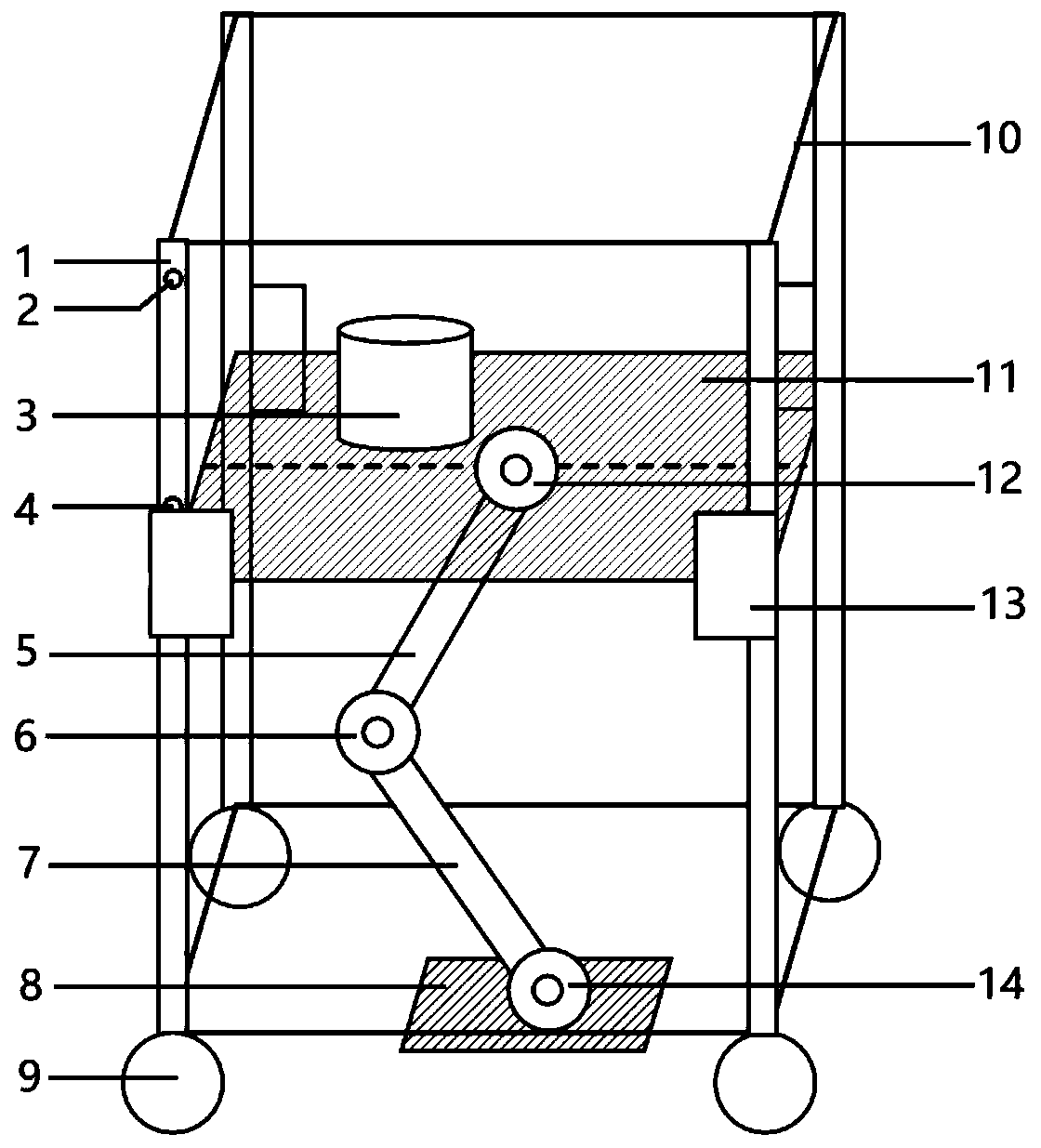
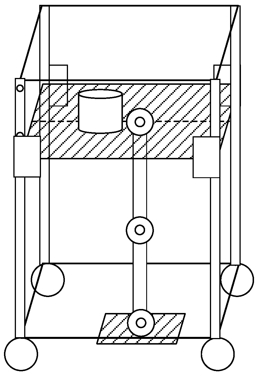
[0020] see figure 1 and figure 2 , the foot joint bionic robot leg joint dynamic test platform of this embodiment is made up of platform support, slide rail, simulation plate, position sensor, counterweight and tested robot joint; Wherein, platform support comprises two square frames 10, four Slide rail 1, four sliders 13 and four universal wheels 9, two square frames 10 are respectively located at the upper end and the lower end of vertical slide rail 1, and play the role of lateral support. The sliders 13 are respectively connected with the vertical slide rails, and can move up and down along the slide rails 1. The sliders 13 have a locking function;

[0021] The simulation panel includes an upper simulation panel 11, a lower simulation panel 8, a hip joint electric drive module 12 and an ankle joint electric drive module 14; the upper simulation panel 11 simulates the upper part ...


PUM


Abstract

The invention discloses a dynamic testing platform for leg joints of a foot-type bionic robot. The dynamic testing platform is composed of a platform bracket, a sliding rail, simulation flat plates, aposition sensor, a balancing weight and tested robot joints, wherein the upper simulation flat plate simulates the upper part of a body and connected with a hip joint electric driving module, and thehip joint electric driving module can be detachably replaced with a rotating shaft, so that the motion characteristics of a single joint are tested; the lower simulation flat plate simulates the feetand makes contact with the ground, and an ankle joint electric driving module is connected with the lower simulation flat plate; and thigh bars of tested legs, a knee joint electric driving module and shank bars of the tested legs are connected between the upper simulation flat plate and the lower simulation flat plate. The demands of various motion modes such as squating, standing-up, walking, running and jumping of robots with different weights for the torque, the rotating speed and the power trajectory of the electric driving modules can be accurately analyzed, the overall motion state andthe load capability situation of the leg electric driving module of the robot can be tested before assembling, and a lot of the time and costs are saved.

Description

technical field [0001] The invention belongs to the technical field of robot performance testing, and in particular relates to a dynamic testing platform for leg joints of a footed bionic robot. Background technique [0002] The movement characteristics of the footed bionic robot in discontinuous contact with the ground enable it to adapt to complex terrain such as mountains, next door, grassland, etc., and has a larger range of motion than wheeled or tracked mobile robots. The joint is one of the core components of the footed bionic robot. The electric drive module composed of motor, electric control, and reducer has the characteristics of precise control and fast response. It has been extensively studied in the field of footed bionic robot joints. [0003] The leg movement of the footed bionic robot involves the joint action of three electric drive modules at the ankle joint, knee joint and hip joint. Accurate analysis and testing of the combined motion of the three elect...

Claims


Application Information

Patent Timeline
Patent Type & Authority Applications(China)
IPC IPC(8): G01M13/02
CPCG01M13/02
Inventor 汪远林窦满峰王婷雷红胜张晨秦浩然
Owner NORTHWESTERN POLYTECHNICAL UNIV
Learn More